ppPLUS: Technologies and more
Go to Homepage to browse companies and process data
ppPLUS-Solutions providing Services and Support
Register creating your own models
Technology

- Name
- QB JOHNSON Glycol Dehydration
- Owner
-
/ QB JOHNSON MANUFACTURING, INC. - Brand
- GLYCOL DEHYDRATION UNITS
- Process
- Gas processing
- Type
- Glycol Dehydration
- Available
-
QBJ has the experience and design capabilities to engineer and manufacture new Glycol Dehydration Units ranging from 60 MSCFD up to and including 450 MMSCFD. QBJ has also designed Units that have met Pipeline specifications of less than 1 pound per MMSCF.
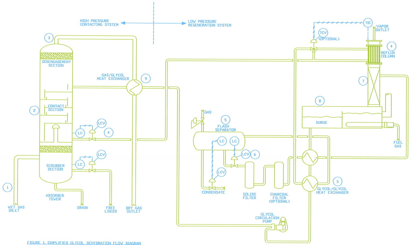
The Dehydration Process is straightforward; Saturated Gas comes into contact with Lean TEG, allowing the TEG to absorb the Water from the Gas. The Figure illustrates how a TEG Dehydration Unit removes Water Vapor from Natural Gas.
- lnlet Gas enters the Scrubber Section of the Contactor where free Liquids are separated and level controlled to storage; free Liquids are separated to prevent Glycol Contamination and subsequent damage to the Regenerator.
- From the Scrubber Section, the Wet Gas enters the Absorber where the Lean TEG contacts the Gas and absorbs the H2O.
- The Dehydrated Gas Stream exits the Absorber Contact Section and flows upward through the extended Disengagement Stage prior to final Separation and exits through the Top Outlet.
- The water rich TEG is level controlled from the Glycol Accumulation Section of the Contactor to the Reflux Condenser Section of the Still Column where the cool TEG provides a reflux source to reduce TEG losses from the Still Column.
- From the Reflux Condenser, the TEG contÌnues to the Lean Rich HEX where it is preheated prior to entering the 3-Phase Flash Separator where Flash Gas (including flashing BTEX Aromatics) is separated from the TEG. ln addition, the Bucket and Weir Section separates and removes Liquid Hydrocarbons.
- The Rich TEG is level controlled through the Particulate Filter, Carbon Adsorber, and the Second Stage of the Lean Rich HEX into the Still Column.
- ln the Still Column, the Water Vapor is stripped from the TEG and exits through the Reflux Condenser and the Still Column. The partially stripped TEG flows downward to the Regenerator where the TEG is re-concentrated at approximately 400°F (204.4°C) prior to flowing into the TEG Surge section.
- Lean TEG exits the Surge. TEG flows through both Sections of the Lean Rich HEX before being pumped to the TEG / Gas HEX where TEG is cooled to within 10"F of the Gas temperature exiting the Absorber.
- The Lean TEG flows from the TEG / Gas HEX to the Top Tray of the Absorber where it begins its downward Absorption path. The diluted (Rich) TEG is accumulated in the Bottom, and the Dehydrated Gas flows to the Sales Line.
- Link
System Info
- Updated by
-
 Kokel, Nicolas
 - Updated
- 1/29/2023 5:18 AM
- Added by
-
Kokel, Nicolas
- Added
- 1/29/2023 4:58 AM
No Services yet available.
Enquire in Solutions how we can help you.