Technology Type
- Type
- Crude Atmospheric Distillation
- Process
- Crude Oil Processing
- Abbreviation
- ADU
-
Crude Oil Atmospheric Distillation Unit
Atmospheric Distillation is the first and the most fundamental step in the Refining Process because it aims to separate Crude Oil into fractions for further Processing by other Processing Units, that means it cannot be placed somewhere else in the Refinery and definitely not set aside.
After being extracted, the Crude Oil goes through some Treating Processes such as Desalting in order to avoid any complication (Corrosion, Impurities…) in the Process of Distillation or further. The objective of crude distillation is to fractionate/separate Crude Oil into Light-End Hydrocarbons.
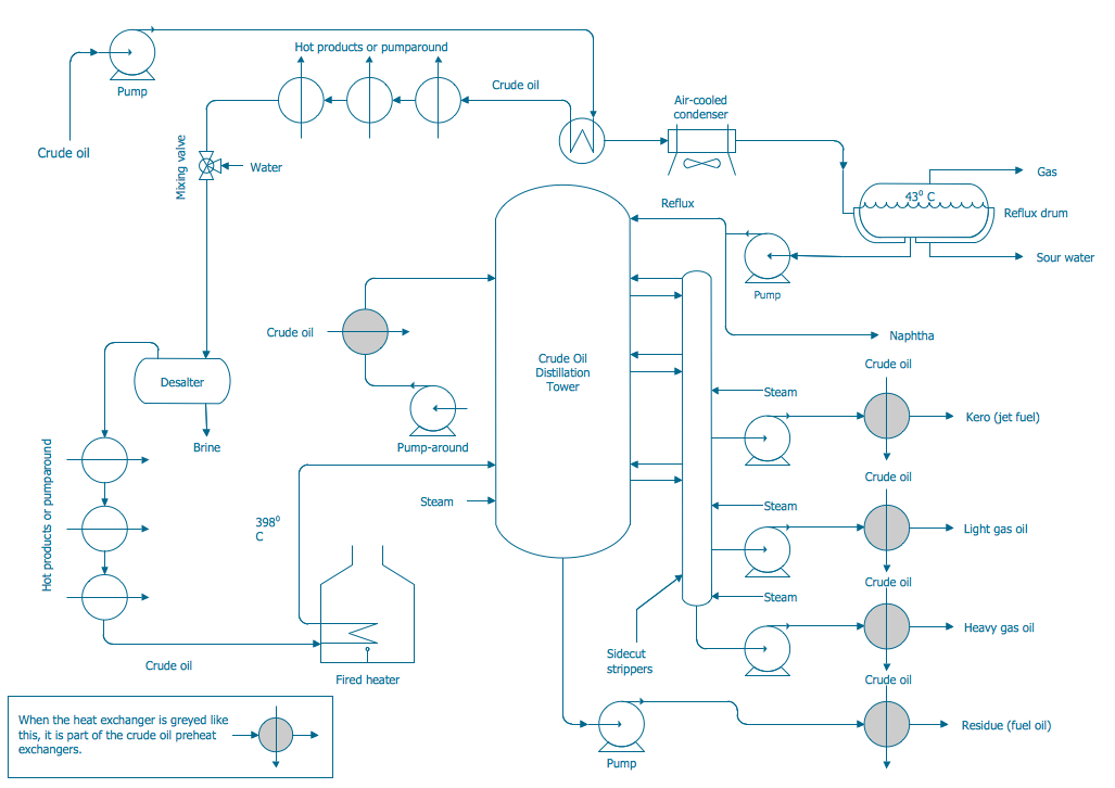
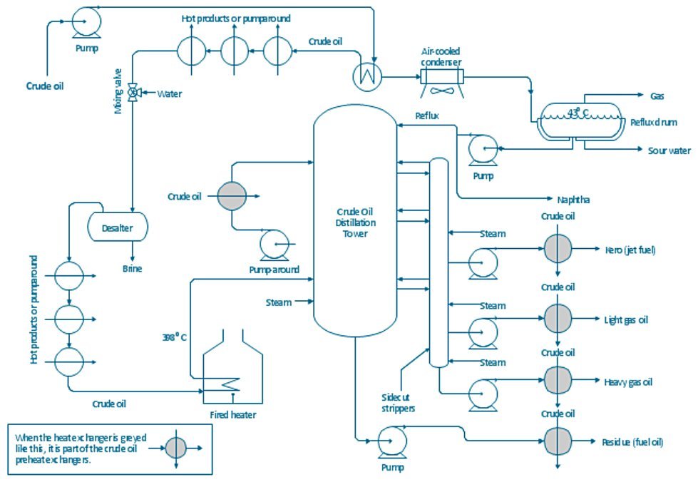
It is carried out in a Tower/Column, known as Atmospheric Tower, Atmospheric Distillation Unit (ADU), Pipe Still, Crude Unit, Crude distillation Unit (CDU), Fractional Distillation Column as shown in Fig 1 at a pressure slightly above the atmospheric (around 1-3 atmosphere), and a temperature below 380°C (T°? 380°C) to avoid undesirable Thermal Cracking at higher temperature.[1]
Figure 1 - Crude Oil Atmospheric Distillation Process Flow Diagram[2]
When pressure in the Distillation Column increases, the Separation of two Components will be difficult because the volatility decreases and that is why the pressure in our case is maintained slightly above the Atmospheric: to raise the boiling point of the Fractions and separate them, also if the pressure is below atmospheric (vaccuum) the temperatures decrease and the boiling points of the estimated fractions cannot be reached.
The ADU consists of a Vertical Shell where Separation of the Liquid Components is done, Column Internals referred to as Trays or Plates to facilitate contact between the Vapor Phase and the Liquid Phase two Sections:
- The Trays between the Bottom of the Column and the Feed Tray called Stripping Section, aiming to concentrate the heavier Component in the Liquid Phase.
- The trays between the Feed Tray and the Top of the Column called Rectifying Section aiming to concentrate the lighter Component in the Vapor Phase.[1]
Atmospheric Distillation Process Details
After heating up the Desalted Crude Oil to the required temperature, it is flashed in an Atmospheric Distillation tower at 1.2~1.5 atmosphere pressure. In the ADU, the main Fractions having specific boiling-point ranges and volatility are separated into Gases, Light distillates, Middle distillates, Gas oils, and Residuum.
The Fractions removed from the Side of the Distillation Tower at various points between the Column Top and Bottom are called Sidecuts. Each of the Sidecuts (i.e., the Kerosene, Light Gas Oil, and Heavy Gas Oil) is cooled by exchanging heat with the incoming Crude Oil Feed.
Hot flashed Vapors in Crude oil move up in the Distillation Tower and interact with the Condensed Liquid coming down. The lightest Vapors of Gases and Naphtha move upwards while heavy Vapors are condensed and move downward. Cold Streams of Reflux in the Tower cause Condensation of heavy Fractions and cause them to move downwards. Further, condensed Fractions are taken off at different Parts of the Tower according to their condensation temperature. The un-condensed Gases and Naphtha are removed from the top while the un-vaporized part of Crude Oil that leaves from the bottom is called the Residue.
Low pressure Stripping Steam is provided at the Bottom of the Column to remove any light Hydrocarbons from the Residue and enhance the Flashing of the Crude Oil. Stripping Steam reduces the partial pressure of Hydrocarbon Vapors and causing them to boil at low temperatures. The stripped Residue called Reduced Crude, leaves from the Tower Bottom and is either utilized for Heat Recovery and cooled down as a Product or passed to the downstream Vacuum Distillation Unit (VDU) for further processing.
The Top Reflux consists of condensed Naptha is used to control the Tower Top temperature. A high flow of Reflux will reduce the top temperature and will reduce the endpoint of the Naphtha Product. But top temperature must be controlled sufficiency higher (10~15 degrees °C) than the dew point of the Overhead Vapors.
Re-fluxes play a vital role in the Product Separation and heat integration of the Distillation Tower. The Pump around the section takes the hot Product (Kero, Diesel) for heat recovery and returns back as cold Reflux above the Draw-off Tray. In addition, hot Reflux also returns back below the Draw-off Tray. The purpose of hot and cold Refluxes is to condense the hot Vapors the the maximum possible extent to reduce the Vapor load on the Tower and ensure maximum Separation of the Products.
Furthermore, separated Streams are provided Side Steam Strippers for the removal of lighter Ends from the Products. These lighter Vapors and Stripping Steam are delivered above the Side Stream Draw-off Tray.[3]
Boiling Fractions
Crude Oil Fractions separated in the Atmospheric Distillation Process are shown in Fig. 2. The Vapors from the Top of the Column are a Mixture of Hydrocarbon Gases (e.g., Methane, Ethane, Propane, Butane) and Naphtha vapors, at a temperature of 120°C - 130°C. A few Plates below the Top Plate, the Kerosene is obtained as product at a temperature of 190°C - 200°C. A few Plates below the Kerosene Draw Plate, the Diesel Fraction is obtained at a temperature of 280°C - 300°C. Residual Oil present at the Bottom of the Column is known as Reduced Crude Oil (RCO). The Temperature of the Stream at the Bottom is 340°C - 350°C, which is below the Cracking Temperature of Oil.[4]
Figure 2 - Crude Oil Boiling Fractions and their Uses[5]
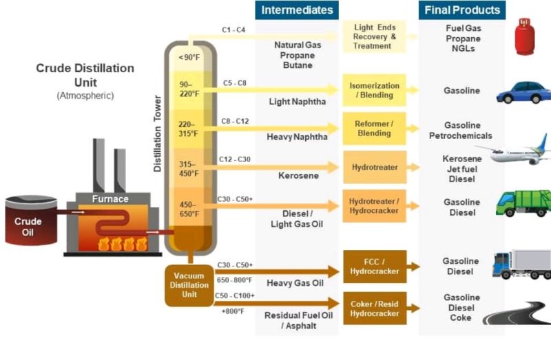
Most of the Fractions (i.e., the Overhead Naphtha, the Sidecuts, and the Bottom Residue) are sent directly to the downstream Processing Units called Straight Run Products. While some Products may also be stored in intermediate Storage Tanks before being processed further. Moreover, some part of the Straight Run Products is also blended with the Final Product.[3]
Fractions Percentages
The yield of different Distillation cuts from Crude Oils vary with the specific gravity of the Oil. Light Crudes have a high content of Light and Heavy Naphtha and relatively low content of Vacuum Gas Oil and Residue, compared to Heavier Crudes. The content of Kerosene, Light and Heavy Atmospheric Gas Oil (Diesel) do not vary that much with Whole Crude gravity. Examples of the type and percentage of the Fractions obtained by Crude Oil Distillation are presented in Table 2 and Table 3[6] and Fig. 3[7].
Table 2 - Fractions obained from Arabian Crude[6]
Fractions Percent
YieldN° of Carbon
Atoms in MoleculesBoiling
Range (°F)Gases (dry/wet) 2 1-2
3-4-260 to -130 dry
-55 to 30 wetNaphtha 20-26 5-12 90-360 Kerosene 7-12 10-15 320-460 Diesel Oil 10-14 12-20 400-600 Wax Distillate 15-20 17-22 500-700 Residuum 35-40 20-90 600+ Table 3 - Crude Distillation Products[6]
Fractions Yield (wt%) True Boiling Temperatures Atmospheric Distillation (wt%) (°C) (°F) Refinery Gases (C1 - C2) 0.10 - - Liquid Petroleum Gases (LPG) 0.69 - - Light Straight Run (LSR) 3.47 32_82 90-180 Heavy Straight Run (HSR) 10.17 82-193 180-380 Kerosene (Kero) 15.32 193-271 380-520 Light Gas Oil (LGO) 12.21 271-321 520-610 Heavy Gas Oil (HGO) 21.10 321-427 610-800 Vacuum Distillation (wt%) (°C) (°F) Vacuum Gas Oil (VGO) 16.80 427-566 800-1050 Vacuum Residue (VR) 20.30 +566 +1050 Figure 3 - Assay - Global Crudo Oil Markers[7]
.png)
Oil Fractions Yields vs. Whole Crude Density
Table 3 shows Assay of nine different Crude Oil also mentioned in Fig. 3 above, with lower APIs resulting in higher proportions of Middle Distillates and Atmospheric Residue. It is important to note the assays of the two LTOs (Bakken and Eagle Ford) with their higher gravities and Naphtha yields.[7]
Table 3 - Assay - Crude Oil Markers vs. API[7]
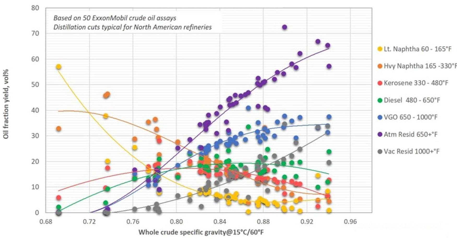
Crude API Sulfur GasToC4 LN HN Kero Gasoil Resid Bakken 41.0 0.2 1.1 13.6 23.5 11.9 21.1 28.7 Eagle Ford 47.0 0.1 1.0 11.6 22.4 15.0 23.0 27.0 WTI 40.0 0.3 1.5 5.7 24.1 14.9 23.5 30.2 LLS 35.8 0.4 2.5 7.6 16.6 12.4 26.4 34.5 Forties 40.3 0.6 2.9 8.5 21.4 10.6 24.5 32.2 Brent 38.1 0.4 2.7 6.8 14.4 13.3 26.1 36.7 Urals NWE 35.8 0.2 2.6 3.0 14.3 8.9 25.2 46.8 Bonny Light 35.1 0.2 1.2 6.1 17.6 10.7 38.7 25.9 Maya 21.1 3.3 2.0 2.4 12.0 12.0 11.9 59.7 Fig. 3 shows the yield of Distillation Cuts typical for European refineries, while Fig. 4 shows yields of Distillation Cuts typical for North American Refineries. The data used in the figures are from Crudes from all over the world. The differences in the Refinery Fractionation cut points are caused by differences in the fuel marked. North
America has a larger Gasoline marked than Europe, and Gasoline is made from the Naphtha Fraction. Europe has more diesel cars, and a resulting larger need for Gas Oil (from which the Diesel is made) from the Crude Oil. The differences in demanded volumes are met by varying the cut point temperatures between the different Fractions, but also by selecting different Cracking Processes for the VGO and Residue, favouring Naphtha or Gas Oil Production.[8]Figure 4 - Yield of Crude Oil Fractions as Function of Whole Crude Specific Gravity - European Refineries[8]
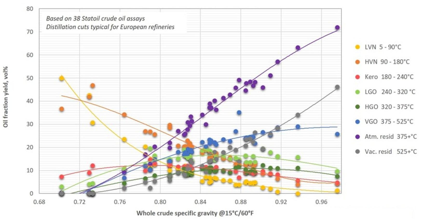
Figure 5 - Yield of Crude Oil Fractions as Function of Whole Crude Specific Gravity - US Refineries[8]
References
- Arab Oil Natural Gas, what is Atmospheric Distillation? (accessed 12th Nov 2023).
- CS Odessa, CC BY 4.0, via Wikimedia Commons, File: Engineering-Chemical-Process-PFD-Crude-Oil-Distillation-Unit.png.
- Nasir Husain, 6th Jan 2021, Crude Oil Distillation Unit, THE PETRO SOLUTIONS.
- U.S. Energy Information Administration (EIA), 5th Jul 2012, Crude oil distillation and the definition of refinery capacity.
- Valero Energy, 2020, Refining 101: Distillation Basics @ 45 sec, Youtube.
- Dokumen, Petroleum & Petroleum Products (accessed 11th Nov 2023).
- Max Pyziur, 4th Feb 2015, CONDENSATE, An EPRINC PRIMER, Energy Policy Research Foundation Inc.
- The Engineering Toolbox, Yield Stucture of Crude Oils wih Increasing Density of Crude (accessed 11th Nov 2023).
- Link
System Info
- Updated by
-
 Braun, Uwe
 - Updated
- 11/12/2023 5:58 PM
- Added
- 11/9/2021 5:49 AM

No Services yet available.
Enquire in Solutions how we can help you.

Image
Video
Technologies
| Technology | Owner | |
|---|---|---|
| Technology | Technology Entity | |

|
SULZER |
