The aim of this brief article is to highlight the major process features of mixed feed steam cracker which plays a crucial role in meeting the needs of the integrated refinery petrochemical complex. The numbers mentioned in the text are indicative and only serve to highlight the ballpark range.
Introduction:
A Mixed feed steam cracker represents a crucial unit in the refinery - petrochemical complex. Whereas an Ethane gas cracker is set up to produce only Ethylene, a Mixed feed steam cracker (MFSC) has the capability to process both gas and liquid feeds separately and can produce a broad slate of products such as Ethylene, Propylene,C4's / C5's, pygas and residual pyoil. The BTX is extracted from the hydrogenated pygas and the raffinate is recycled back to the MFSC.
As Toluene is in excess of demand, it is normally upgraded to Benzene and Mixed xylenes. Again, the concentration of mixed xylenes isomers and amount would decide if there is a need for a dedicated para xylene unit with its associated downstream process or mixed xylenes be sold outside the battery limit. Benzene can further move up the value chain by conceiving downstream products associated with it. In case of crude C4's train, a plethora of choices exist depending on the market demand. They can be either:
i) fully hydrogenated and sent back to the MFSC,
ii) Extract Butadiene and
iii) selectively hydrogenate the raffinate to produce Butene-1 and Butene-2 and further MTBE as well, if needed,
iv) catalytically crack the crude C4's to boost the Propylene.
In cases where Butadiene is extracted and selective hydrogenation is done, the raffinate is then hydrogenated and fed back to the MFSC. There are technology licensors available for these and depending on the client requirements, the C4's and Aromatics train can be configured.
The route that Ethylene producers take is heavily dependent on the availability of cheap raw material and therefore it is region dependant. So, it is noticed that in Middle East and in the US, due to the abundance of ethane and shale gas, Ethylene is dominated by gas cracker route. In India, China and other Asian economies, naptha is the predominant feedstock. As naptha is closely tied to crude prices, this introduces an element of vulnerability in raw material price. Globally, Ethane makes up around 46% of the Ethylene feed and Naptha makes up around 43 %. This would shift with greater emphasis now on integrated refinery petrochemical complexes especially in Asian region and probably a balance will be achieved between gas and liquid feedstocks globally.
Ethylene yield is 80 wt% in an Ethane cracker and ~ 33 wt% in a naptha cracker. The % of the pygas (aromatics rich liquid in C5-C12 range) depends on the feedstock used and it varies from 1.5 wt% in an Ethane cracker to about 16 wt% in a light naptha cracker (high severity). The residual pyrolysis fuel oil is around 3 wt% in the case of naptha (high severity) and if Atmospheric gas oil is used at high severity, then it is around 17 wt%.This is because gas oil consists of a good amount of napthenes and aromatics, which while passing through the cracker deposit coke and yield higher aromatics at the temperatures encountered. The typical coil outlet temperatures used between a high severity naptha cracker and ethane cracker is around 8500C - 8800C and the residence time ranges from 0.1 to 0.6 seconds depending on feedstock and severity used. Steam is added as a diluent in order to lower the partial pressure of the reactant to push the equilibrium towards more olefins and to prevent coke formation. The ultimate yields depend on key variables such as i) coil outlet temperature ii)steam to hydrocarbon ratio iii) residence time and iv)type of feed used (1),(3). The cracking severity is controlled by the coil outlet temperature and it is indicated by the P/E ratio (Propylene/Ethylene). P/E can be altered to meet the product requirement in a MFSC.
Fresh Ethane and Propane are fed into separate furnaces with recycle furnaces configured to crack them in separate coils in a furnace. This is because Ethane is more sluggish kinetically as compared to Propane and would need higher cracking temperatures. In case of LPG, due to its similar reactivity with naptha, it is sometimes mixed at an appropriate blend ratio and processed together in plants. In case of gas oil, it would normally be fed into a separate furnace because of its differing reactivities as compared to naptha. In some cases, a proportion of naptha and gas oil can be mixed and fed as well.
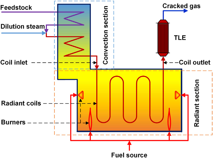
The layout for a generic steam cracker consists of:
i) a convection zone where the hot flue gas from the furnace is used to extract heat in order to heat up the feedstocks
i) a radiant section where the pyrolysis takes place and
iii) a quench section where the hot product stream is rapidly quenched in order to prevent degradation. Once the product gas stream is quenched, it then moves into downstream section via quench tower and CGC, where the configuration can take different forms depending on the specific project requirement, namely:
a) front end demethanization
b) front end depropanization or
c) front end de ethanization.
Several improvements over the years have been demonstrated commercially by technology licensors in the Furnace, Transfer Line Exchanger, Cracked Gas Compressor, Cold box, Refrigeration cycles, Distillation columns and in C2 /C3 tail / front end hydrogenation reactors.
The figure below shows the structure of a steam cracker unit (2)
The steam cracking technology is dominated by handful of licensors - Technip, Lummus, Linde and KBR. These licensors have unique capabilities in terms of their furnace design, coil geometry, residence time, decoking cycles and downstream configurations. Each of these licensors have developed expert in house steam cracker furnace modeling capability. The table below gives the coil features of the licensors :
Coil features of Technology licensors(3)
| Licensors | Design |
| Technip | SMK & USC-M (gas); GK6 & USC - U coils (liquid) |
| KBR | SCORE SC-1 |
| Lummus | SRT VI |
| Linde | PyroCrack |
Over the years, many improvements in design have been made in Steam cracker technology and today, a world scale gas cracker can go upto 1.8 MMTPA Ethylene (Yossemite - Exxon/SABIC plant) and for liquid cracker, as high as 1.5 - 1.8 MMTPA (AMIRAL, SADARA, Borouge). Likewise, the capacity of single furnace has moved upto 200-250 KTA, whereby advantages can be taken of the economies of scale.
Recent Developments:
The trend towards greater use of EV has led to an expected dip in fuel off-take from refiners. This has picked up noticeably in China and is catching up in India and other developing economies. This is expected to lead to a displacement of 5 MB/day gasoline and diesel consumption by 2030. Additionally, the rise in petrochemical products outstrips the expected growth in demand for transport fuels, per barrel of crude. Therefore, it is projected that demand for petrochemicals from crude would increase by ~ 5 MB/day from 15.5 MB/day in 2024 to around 20 MB/day by 2050 (4).
As has been written in earlier expert articles in this platform, refiners would be looking more towards integrated refinery - petrochemical complexes to take advantage of this shift. So, the feedslate for a conventional MFSC will see a feed shift from ethane/propane/LPG - naptha to ethane/propane/LPG - naptha/gasoil. This places some points which need to be considered before selection of the unit.
Factors to be considered:
The liquid feed considered here is restricted upto hydrotreated gas oil. This has FBP in the range of 500-550 deg.C, and would need to be completely vaporised in the convection section before it enters the furnace. Incomplete vaporization of the liquid feed would lead to deposition of coke on the unit, reducing the run time. So, the furnace design would need special emphasis in order to ensure this is not happening. In the convection section, the specific vaporization characteristics of the liquid needs to be taken into account to ensure that the liquid feed is completely vaporized by the time it leaves the section. The cross over temperature would need to be carefully handled to ensure that it doesn't exceed the cracking temperature before it reaches the furnace. This is because gas oil is more reactive than naptha and would crack at lower temperature. Extensive pilot trials with actual feeds coupled with kinetic modelling can help arrive at this value.
As compared to only naptha, gas oil due to its high molecular weight would need more steam dilution in order to lower its partial pressure and prevent coking in the furnace and to also lower its boiling point. A typical steam dilution is around 0.8 - 1 as compared to 0.4 - 0.6 in naptha case. Another point to be noted is the strict control of the residence time. As gas oil is more reactive, its residence time in the furnace needs to be shorter than that of naptha. A typical atmospheric gas oil furnace operates at coil outlet temperature of about 8200 C with a residence time of less than 0.3 seconds(3). Therefore, the coil geometry and length as well as the flow pattern play a major role in ensuring this. Flow is highly turbulent in order to ensure uniform concentration and temperature profile radially and evolving profiles axially, thereby approximating ideal plug flow. The residence time and the coil outlet temperature are linked. The residual pyrolysis fuel oil represents a degradation of Carbon and therefore MFSC using hydrotreated gas oil are normally cracked at high severity in order to reduce this amount. Mixed feed steam crackers using gas oil run the risk of lower run time due to coking tendency because of the heavier carbon molecules present in the liquid feed. So, the decoking cycle would be a major factor.
Energy intensity (GJ/ton of product) is a major consideration. In the case of MFSC using these types of feed in an integrated complex, its usually reported as GJ/(ton of Ethylene + Propylene). The energy intensity of steam crackers normally aspires to be in the 1st quartile. To give a ballpark value, the Energy intensity for Ethane cracker is around 16 GJ/ton of Ethylene and for a naptha cracker it is in the ballpark of 23 GJ/ton of Ethylene(5). Naptha crackers have higher energy intensity due to the bigger molecule size which needs to be vaporised at high temperatures and the subsequent downstream load. However, as benchmark data on these types of heavy liquid feedstocks in integrated refinery - petrochemical complexes are scarce, generally, the Energy intensity is targeted to meet the site requirements. Probably, going forward Solomon index would capture the benchmark, if not done already. The CAPEX intensity of the MFSC is another very important consideration in the overall economics of the complex.
In order to comply with the carbon footprint reduction, the option of enabling MFSC with Hydrogen burners wherever possible and practical is being looked at. The viability of this depends on the region in which the plant is located. A MFSC flue gas contains mix of CH4 and H2 , the ratio of which depends on whether it's a gas feed or a liquid feed(1). So, the scheme would route this CH4 into a Steam methane reformer (SMR) and generate additional H2 to be used as burner fuel. This depends on the price of the SMR unit and cost of the fuel used. Alternate approach is to generate H2 using renewable sources, which has issues of cost and scale and depends a lot on subsidies. The burner tips would need to be redesigned in case pure H2 is used.
Several studies have been reported by licensors on electrical furnaces at pilot scale with huge potential to reduce the energy consumption in the furnace(6). The success of electrification in the furnace depends largely on the reliability of supply and on the cost of electricity. This is because Olefins are commodity chemicals produced at a massive scale and they would need to run continuously without interruption, other than that for routine maintenance. The furnace and the convection section design would need to be relooked into because this is a different method of imparting heat energy. However, in order to reduce the Carbon footprint of existing plants, some key equipment's such as compressors have been electrified in some plants.
Additionally, the concept of digital twin in order to benefit from real time forecasting and monitoring is now gaining traction.
In summary, Mixed Feed Steam cracker is a versatile, well proven and reliable route to producing olefins, aromatics and C4/C5's. It has decades of successful plant runs which have run consistently at world scale capacities. Successive technological improvements over the years have further boosted its reliability. This is now being fully leveraged to be a vital part of the integrated refinery-petrochemical complexes.
References:
1. Steam cracking of Crude Oil, IHS PEP 29J (2016)
2. Steam Cracking Technology Type, ppPLUS
3.Ethylene, Nexant PERP (2013-4)
4.Oil, IEA (2025)
5.Decarbonization approaches for Ethylene Production, Green Chemistry (2025), P 3655-3675
6.Electrification of Process Plants, Nexant (June 2025)
|
Dear Sirs Thank you for the good article. Yes Gas Cracking has its own advantages in the Middle east where gas is avaiable in plenty and cheap. Companies preferentially produce a lot of ethylene as the conversion is high. They are keen to cnsider metathesis also for Propylene. The situation in the Asian subcontinenet is somewhat different:
Regards
|