Mega Scale Olefin and Petro FCC in Integrated Complex – Dream Project

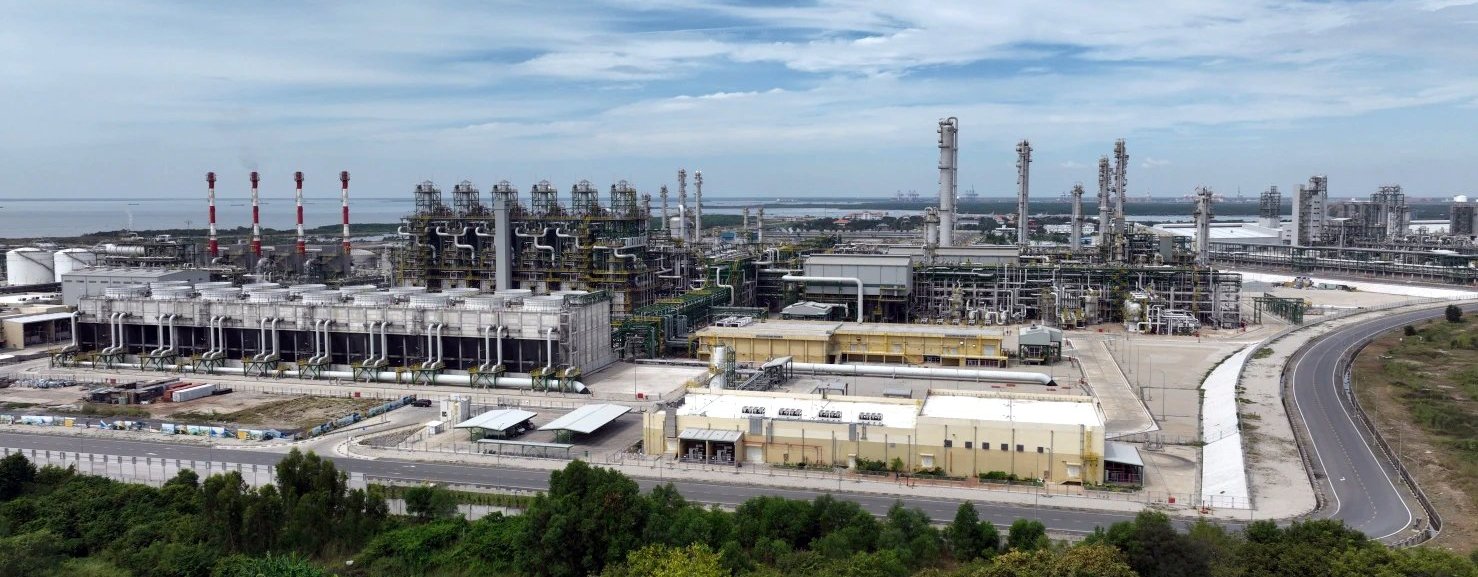
Photo: Example of a fully integrated olefin complex (SCGC’s LSP, Vietnam, Dec 2023)
|
|
|
The interest in the Mega Refinery Dream Project is building up. This has further gained momentum pursuant to the Live session arranged by PP plus. While all queries are being addressed, some generic aspects with respect to maximization of the Intermediates for Petrochemicals, has been a subject of interest for many readers. As has been clarified in various sessions, the central upgraders of the Complex are Petro FCC and Olefin complex, as well as CCR designed to maximize Aromatics. The issue however, revolves around the mega Size of Petro FCC and Olefin complex to serve the Objective function of maximizing the production of intermediates viz: Ethylene, Propylene, para Xylene and Benzene. As has been highlighted in the sessions, the feed-stock diet of the Plants is the key to ensure that large capacity installations are created to meet the overall objective.
Salient Considerations for Feed-stock Diet of Cracker, PFCCU
Cracker Feed
1. The complex addresses a 20 MMTPA throughput of Crude mix of AL: AH in 50:50 ratio. This itself ensures a relatively smaller bottoms upgradation of VR and larger produce of lighters to maximize Petrochemicals from the complex.
2. Since LPG remains a preferred product in the country, Straight run and Cracked LPG in the complex is used as commercial product, rather than feed-stock to Cracker which otherwise should be its preferred destination.
3. Light Naphtha (LN) routed entirely from CDU directly to Steam Cracker after hydro-treatment.
4. Heavy Naphtha (HN) routed to CCR Platformer for aromatics (BTX) production to a capped total capacity of 1.2 MMTPA of PX including recovery from Py-gas from Cracker. Surplus hydro-treated HN after meeting CCR requirements to be directed to Steam Cracker.
5. Surplus Light Kerosene routed to Steam Cracker as a high-paraffin feed-stock after meeting a capped production of 1 MMTPA of ATF from the complex.
6. PFCC & DCU Off-gases routed through a centralized Gas Recovery Unit (GRU) to recover ethylene, propylene as products and ethane and propane as recycle streams for cracking to extinction in Cracking Furnaces.
7. All propane from PFCCU routed to Cracker.
8. DHDT naphtha from the Mild Hydrocracking at 35% conversion along with the naphtha from VGO Hydro-treater and SHCU are routed to augment Steam Cracker feed pool.
9. DCU naphtha shall be hydro-treated in central Naphtha Hydro-treater for separation of light and heavy naphtha before being routed as Cracker feed.
10. C4 Mix could be Hydro-treated and recycled to cracker. Since LPG production is recommended, unsaturated LPG from PFCC & DCU would not be available to support a K-COT unit.
11. Maximize paraffinic content in the Steam Cracker to be ensured by routing hydro-treated LN, surplus HN, light kerosene, and paraffinic DHDT/SHCU naphtha while keeping heavy, aromatic-rich streams out of Cracking furnaces feed.
12. Operate the cracking furnaces at high coil outlet temperatures (COT) and short residence times to maximize ethylene selectivity.
13. Total Cracker Feed to be around 5.7-5.9 MMTPA excluding the off-gases from DCU and PFCCU.
14. Total propylene production from the Cracker could be about 0.8-0.9 MMTPA while the total ethylene production could be 2.1-2.2 MMTPA.
Maximizing Propylene Production
1. The PFCC to be optimized to operate at high riser temperatures and short contact times. Utilize ZSM-5 additives in PFCC to crack feedstock for achieving minimum 20% propylene yield.
2. The total Propylene pool shall comprise of Propylene from Cracker & PFCCU.
3. The total propylene production could be to the tune of 1.9 MMTPA
Maximizing PX and Benzene Production
1. CCR Platformer to be operated at high severity to maximize the aromatic yield.
2. Aromatics Complex to include Extractive Distillation followed by dedicated PX recovery unit, for maximizing recovery.
3. Hydro-treated Py-gas to be integrated with Aromatic Recovery section to maximize recovery. Typically, 40% to 45% of total Py-gas shall be BTX component.
4. A Toluene Disproportionation unit to convert lower-value Toluene and Benzene streams into high-purity Paraxylene (PX) and heavier xylenes to be incorporated for maximizing total PX output.
5. Total PX to the tune of 1.2 MMTPA and Benzene to the tune of 500-600 KTPA can be anticipated from the complex.
Cracker Complexities and large size Equipment
For such a large Cracker following are some of the major equipment and associated complexities, which will have to be addressed:
Cracking Furnaces
1. The furnace island will require a modular battery of high-capacity twin-cell pyrolysis furnaces of designs commonly prevalent SRT IX/X Lummus, Linde Pyro-Crack or Technip SRT coils.
2. Two twin cell furnace could be dedicated to PFCCU Propane and Light Naphtha (CDU + NHT LN) Operating at high coil outlet temperatures (COT ~830–850°C) and short residence times to maximize ethylene yield.
3. Two twin furnaces dedicated to Surplus Heavy Naphtha, Light Kerosene, VGO HDT/SHCU Naphtha, and DHDT / Mild Hydrocracker naphtha.
4. One furnace dedicated strictly to cracking the recovered/ recycled ethane and propane for cracking to extinction.
5. Twin-cell design allows for independent decoking of one cell while the other operates, ensuring continuous high-severity operation for heavy paraffinic chains.
6. State-of-the-art steam cracking furnace technologies offered by leading licensors like Lummus Technology advanced SRT firebox design, Linde with PyroCrack, and Technip with SRT coils have scaled up single furnace capacity dramatically to support mega-crackers.
7. Modern high-capacity modular pyrolysis furnaces achieve single-furnace ethylene production capacities of up to 300 KTA of ethylene per furnace depending on liquid vs. gas feedstock.
8. Licensors utilize a twin-cell configuration within a single structural firebox. This allows independent feedstock allocation in each cell for e.g., cracking light paraffinic naphtha in one cell while processing heavier kerosene or recycled ethane/propane in the other. This also enables online decoking—where one cell operates in cracking mode while the other undergoes decoking, ensuring maximum annual run availability.
9. A total of 4+1 dual cell liquid cracking and one dual cell Recycle gases furnace can be envisaged. A twin-cell configuration typically, houses two independent radiant heating chamber cells inside a single structural furnace box with a common convection section, stack, and heat recovery system.
10. Each high-capacity mega-furnace box would be roughly 25m length × 18m width × 35m – 45 m height inclusive of radiant box, convection section, and stack.
11. Typically, 15–20 meters clear separation between each furnace and associated equipment may be required. This will control the plot area around the furnaces.
Compressors
1. Modern world-scale mega-crackers as built in Korea and Middle East employ ultra-large single-train centrifugal compressors capable of handling up to 1.8 to 2.0 MMTPA ethylene capacity.
2. A high-flow, multi-stage barrel-type centrifugal compressor with inter-stage acid gas removal and caustic washing can be foreseen , also to support this single train without bottlenecks, the downstream cold box will feature optimized plate-fin heat exchangers, with or without high-capacity expanders.
3. A dedicated VHP steam driven propylene refrigeration close coupled to an ethylene refrigeration compressor can be foreseen. These machines meet refrigeration duties of cryogenic section. Could have a common condenser, with ethylene machine being run by extracted steam from Propylene refrigeration compressor.
4. The Ethylene and Propylene fractionator shall be equipped with heat pumps. Heat pumps are used in large complexes, as the boiling points of ethylene/ethane and propylene/propane are extremely close; the columns require massive internal vapor/liquid traffic and high reflux ratios. Running them with conventional cooling water overhead condenser and high-pressure steam reboilers would consume massive energy.
5. A closed-loop heat pump compresses the overhead vapor of the fractionator to raise its temperature and pressure and condense it in the column's own reboiler, effectively recycling latent heat from the top to drive the bottom. This slashes both the cooling water and steam consumption by up to 50–70%.
Capex and Others
1. A grassroots world-scale mega-cracker complex envisaged with integrated hydro-treating, deep residue upgrading, and a massive cryogenic cold box represents a multi-billion-dollar investment. However, heavy sharing of hydro-treaters, gas recovery and treatment and utilization of low-value streams significantly optimizes the overall complex-wide CAPEX compared to standalone units.
2. Opex is highly optimized due to internal feedstock loops and high-energy integration.
3. For ethane / propane Cracking Coils long run lengths of 6 to 12+ months are anticipated with infrequent decoking cycles. For Heavy Liquid Cracking shorter run lengths of 30 to 50 days per cell can be anticipated, due to accelerated coking rates from heavy aromatic/naphthenic precursors. The automated online decoking takes approximately 24 to 48 hours per cell without affecting total plant capacity.
4. Typically, VHP Steam at 105 to 125 bar at high superheat temperatures ranging between 510°C to 540°C is generated in the furnace Transfer Line Exchangers (TLEs). For Heavy liquid cracking yields, substantial VHP steam generation is envisaged which can cater to practically all the steam drive requirements of the unit.
5. For such a mega, complex major towers will be envisaged. For example, in hot section the Quench Tower, Primary Fractionator, and Caustic Tower all are of significant dimensions. The diameters of the columns would range between 6.5 – 8.5 m with heights between 40-60m. Most of these columns are designed primarily for liquid-gas contacting rather than deep fractional distillation, housing multiple beds of structured packing or trays to scrub out H2S and CO2using circulating caustic soda.
6. For world-scale mega-crackers (>2 MMTPA ethylene), the sheer volumetric traffic in the Propylene Fractionator (C3 Splitter) can push calculated column diameters beyond practical shop-fabrication and road-transport limits (traditionally ≈8 meters) or create severe liquid mal-distribution and hydraulic gradient issues across standard cross-flows.
7. Multi-Down-comer (MD) trays and high-performance variants like Koch-Glitsch Superfrac or multi-chordal trays eliminate conventional side down comers, and receiving pans, replacing them with multiple narrow, trough-like down comers distributed tightly across the entire active tray area. They dramatically increase capacity per unit of cross-sectional area. Utilizing high-performance MD trays or advanced structured packing allows to significantly reducing the required column diameter, making a single single-shell tower technically feasible even for massive duties.
8. Designing a single large-diameter tower with diameters between 9–10 meters with MD trays can be used to address large product recovery columns, such as Ethylene and Propylene. This can be highly cost effective as dual columns, to avoid complex split-piping, duplicate overhead condensers, dual reboilers, and increased plot footprint associated with parallel dual towers.
9. For a world-scale mega-cracker delivering ~2.2 MMTPA of Ethylene backed by a single ultra-large Cracked Gas Compressor (CGC) train a Single Mega-Cold Box housing multiple parallel brazed aluminum plate-fin heat exchanger (BAHX) cores within a common structural shell is often preferred.
10. A Single Cold Box avoids the extreme complexity, massive cryogenic valve manifolds, and dual-piping balancing acts required to split sub-zero cryogenic streams across two separate cold boxes.
Recently built large Liquid & Dual Steam Crackers
To benchmark a mega-cracker targeting around 2.0 to 2.2 MMTPA of ethylene through deep refinery integration, several major world-scale projects completed or commissioned recently serve as primary industry references:
1. S-Oil Shaheen Petrochemical Project (Ulsan, South Korea) - Refinery-Integrated Mixed-Feed / Liquid Cracker. Capacity 1.8 MMTPA of ethylene, making it one of the largest single-train steam crackers in the world.
2. ExxonMobil / SABIC Joint Venture - Gulf Coast Growth Ventures (Corpus Christi, Texas, USA). World-Scale Mixed-Feed / Dual Cracker Complex. 1.8 MMTPA of ethylene capacity. Designed for high feedstock flexibility, capable of handling a broad range of liquid and gaseous feeds with massive cryogenic cold boxes and single-train cracked gas compression.
PFCC Feed
1. VGO from vacuum distillation unit routed to VGO Hydro-treater and subsequently, fed directly into a close-coupled Petro FCC (PFCC).
2. VGO HDT to be operated at low severity to preserve maximum feed for PFCCU.
3. The VR is split between the Slurry Hydro Cracker Unit (SHCU) and the Delayed Coker Unit (DCU, capped strictly at 2.4 MMTPA). Liquid products such as HCGO from DCU and VGO from SHCU routed to PFCCU via the VGO hydro-treater.
4. Total Feed to PFCCU to be to the tune of 5 MMTPA plus.
For an exceptionally large 5.0 MMTPA Petro-FCCU (PFCCU)—which scales well beyond conventional refinery FCC sizes—handling the massive catalyst circulation rates, extreme heat release, and high gas volumes requires a balanced configuration as below:
Reactor-Regenerator Configuration: Dual Train / Dual Reactor-Regenerator
Dual parallel reactor-regenerator trains- two identical 2.5 MMTPA trains. A single reactor-regenerator handling 5 MMTPA would require a vessel diameter and catalyst circulation rate that pushes metallurgical, structural, and fluidization mechanics past safe, proven commercial limits. Splitting it into two parallel trains ensures stable fluidization, manageable slide-valve sizing, superior temperature control which is critical for maximizing propylene yield via high-severity operation, and the ability to perform maintenance on one train while the other operates at reduced plant load.
The RR section could be coupled with a Tertiary Separation system followed by a power Expander and steam generator. This could be implemented in two parallel trains to produce about 60-70 MW of power and about 220-250 TPH of HP steam. This would be a huge value addition to help in optimizing the overall steam and power generation facilities.
Main Fractionator Configuration: Single Mega-Shell Tower
Single-shell fractionator tower utilizing advanced high-capacity trays and structured packing could be considered. Unlike the reactor-regenerator metallurgy and catalyst loops, a fractionator tower's limits are primarily dictated by diameter and transportation. This may not be that big a constraint for coastal projects, and the large diameter fractionator shell can be shop-fabricated, sea-shipped, and erected as a single unit. A single tower avoids the complex dual-bottom pump loops, split overhead condensers, and balancing controls required for parallel fractionators.
Main Air Blower (MAB): Two Trains (50% + 50%)
Two parallel centrifugal/axial air blower trains. The oxygen and air volumetric requirements for burning coke of 5 MMTPA worth of heavy feed are colossal. A single MAB would require an unprecedented, high-risk mega-machine. Utilizing two 50% trains VHP steam turbine driven ensures operational safety, provides necessary turndown flexibility, and prevents a total plant shutdown if a single blower experiences a trip or seal failure.
Wet Gas Compressor (WGC): Two Trains (50% + 50%) - Two parallel centrifugal compressor trains for the wet gas recovery section. Similar to MAB, handling the massive overhead gas volume from a 5 MMTPA PFCCU requires reliable compression. Splitting the wet gas load across two 50% parallel compressor trains driven by steam turbines protects the gas plant from catastrophic single-point failure and matches the dual reactor-regenerator train layout perfectly.
Gas Plant / GRU Train Configuration Downstream of Fractionator
Downstream of the main fractionator, the Gas Recovery Unit (GRU) / Gas Plant is typically configured as a single train, though it heavily mirrors the front-end compressor setup. Because the upstream Wet Gas Compressor (WGC) operates as two 50% parallel trains, their discharges combine into a single high-pressure header feeding the amine units, sponge absorber, and fractionation section (deethanizer, debutanizer, splitter). While the front-end reactors and compressors use 50% redundancy for mechanical safety, the downstream fractionation columns and absorption towers are unified into a single mega-train to streamline operation, minimize control loops, and optimize product recovery efficiency.
PFCCU Fractionator Overhead Duty & Size
The main fractionator overhead system handles an immense volume of vapor containing steam, naphtha, and light gases. This will require a huge cooling duty. To manage this colossal duty, the cooling system requires induced-draft air-cooled heat exchangers operating in parallel, and supplemented by trim water-cooled shell-and-tube condensers. A massive cooling deck spanning over 100 meters in length may be required.
Because of large PFCCU capacity staggering overhead volumetric flows, standard single-line designs would result in impractically large, unsupportable pipe diameters. The standard design may warrant two large-diameter parallel overhead vapor lines running from the top of the single mega-fractionator shell to the overhead air-cooler banks; this would prevent line sizes from exceeding extreme limits and could be restricted to 56 to 72 inches.
The above suggests that both the Olefin complex and the Petro FCC will pose serious challenges of Design and Implementation due to their sheer size and complexity. However, the advantages of single train advantages far outweigh the other challenges associated with the implementation of these projects.
All queries are welcome! Click the 'Add Comment / Reply' button here below 👇 👇 👇
#refinery #petrochemicals #integratedcomplex #olefincomplex #fcc #fluidisedcatalyticcracking #steamcracking #olefinplant