Transformation of Haldia Refinery from a Fuels-Lube Refinery to a High capacity CTC Complex

Indicative Configuration for IOCL's Haldia Refinery
India has over a period of time emerged as a major Refining hub as it has consistently built on its refining capacity. The transformation actually took place after 1991, when the Refining sector was opened up to the private sector and major Refining Complexes from Reliance and Nayara group took shape to the extent, that out of 267 MMTPA of the refining capacity that is currently commissioned and operational, close to 36% of the same has been installed and operational in the private sector. Additionally, the private sector has added tremendous complexity and flexibility to the refining operation, which makes these refineries extremely versatile to process the most sour and complex crudes available globally. This is as a matter of fact advantage India!
The Refineries in the Public sector, too have significant refining capacity. Originally, the refineries started as small facilities at a given refinery location, but have grown in capacity over a period of time gradually, through debottlenecking and brown field expansions. This time to time intervention however, makes the plants relatively inefficient, where the specific energy consumption is a little constrained and so are the average utility consumption numbers. To modernize the old facilities, various brown field expansions and projects have been launched to phase out the old and archaic facilities, and replace them with modern , state of the art, energy efficient facilities. This campaign has been launched in several refineries and progressively the capacities of various refineries in the country have been scaled up to 6 to 9 MMTPA and gradually even up to 15-25 MMTPA at certain locations. The prospect of incremental capacities in the various existing refineries due to their lower starting base is bound to remain a somewhat continuous affair.
Most of the refineries in the Public sector domain are predominantly fuels refineries and have gradually been conditioned to process a variety of sour and sweet crudes. With time however, additions have been made in the refineries to add petrochemical facilities by way of horizontal addition of Olefin and Aromatic complexes. From the first decade of 2000 however, the trend has been changing a little, wherein, the brownfield and green field refineries have begun to provide a petrochemical orientation to the complexes. In this process, there has been a flurry of Petro FCCs added to the complexes to facilitate production of first generation of petrochemicals through the Polypropylene route. The important part has been to consistently witness disruption in the market, where the demand of distillates has been moderated, while the demand for petrochemicals remained strong and robust, typically around 1.5 times the GDP. This has prompted the new green field complexes to look more like petrochemical complexes, where Petro FCC and Olefin complexes began to be considered in the base configuration from the initial stages itself. Steadily, the Crude to chemicals component is steadily rising from less than 10% to 26% of throughput.
The Indian PSUs though are still fixated around the 9 MMTPA green field refinery capacity regime, but with time, larger throughputs and Crude to chemicals to the extent of 45-50% are likely to be addressed. This transition is a near necessity as the market is changing and the Configurations are becoming more flexible to address quick swings in product pattern from fuels to petrochemicals at a steady pace. The other important aspect is the returns associated with the investment. On an average the incremental petrochemical produce from the complex leads to higher returns, as the advantage of the differ-entail pricing between fuels and petro-products can be availed. This trend is likely to continue!
In this context it is also important to revisit some of the old refining installations and consider the possibility of giving them shape of a crude to chemical complex, by way of incremental capacity, modernization, utilization of existing facilities to the extent possible and maximizing returns from the complex, to address the larger interests of the Nation. In this article, we shall examine one such facility and examine as to how it can be transformed into a large crude to chemical complex from its current form and shape with minimal investment and maximum returns!
Haldia Refinery
Haldia Refinery, operated by Indian Oil Corporation Limited (IOCL), is strategically located in Haldia, West Bengal, near the confluence of the Hooghly and Haldia rivers. This refinery was commissioned in January 1975, and serves as a lube flagship refinery in eastern India with an initial capacity of 2.5 Million Metric Tons Per Annum (MMTPA). The fuel sector was built in technical collaboration with Technip-Ensa of France, and the lube sector with Industrial Export of Romania. Through various in-house de-bottlenecking initiatives and the addition of another Crude Distillation Unit (CDU), the current refining capacity has grown significantly to around 8 MMTPA. The refinery sprawls across approximately 612 acres of land.
Haldia is distinct as one of the primary producers of Lube Oil Base Stocks (LOBS) and features specialized units for solvent extraction, dewaxing, and hydro-finishing to manufacture high-grade automotive and industrial lubricants. Facilities includes Catalytic Dewaxing Units geared toward producing high-quality API Group II and Group III LOBS, reducing the country’s reliance on lubricant imports.
Over a period facilities to remove sulfur from diesel, enabling the production of eco-friendly, low-sulfur transportation fuels compliant with stringent environmental standards. A Residue Fluidized Catalytic Cracking Unit was added to convert heavier vacuum gas oils and refinery residues into lighter, high-value products like LPG and high-octane gasoline. Later integration of a Hydrocracker and subsequent quality and bottom-of-the-barrel upgrade campaigns significantly transformed Haldia Refinery's operational configuration and yield structure. A Once-Through Hydrocracker Unit (OHCU) was built to convert heavy vacuum gas oils into high-quality middle distillates. Further since Haldia processes significant volumes of high-sulfur and heavier crudes to maintain its lube oil production, it accumulates heavy residues. To eliminate these heavy ends and squeeze higher-value products out of low-value residues, a Delayed Coking Unit (DCU) was included in the configuration. The Coker Gas Oil Hydrotreater Unit treats the cracked gas oils coming off the coker to reduce impurities before further downstream processing.
Figure 1 - Indicative Configuration for Haldia Refinery
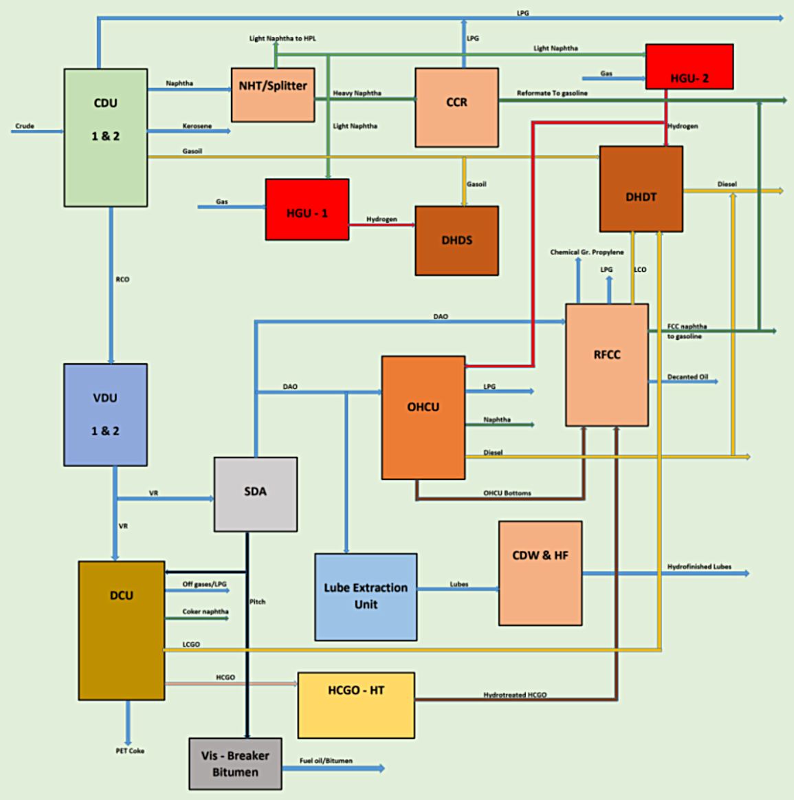
Haldia’s Nelson Complexity Index stands at approximately 9.5 to 9.8. While it started historically as a lower-complexity hydro-skimming and lube-focused plant, subsequent integrations (such as the Once-Through Hydrocracker, Diesel Hydrod-esulphurisation, and the Delayed Coking Unit) transformed it into a medium-high complexity cracking and conversion refinery. By incorporating the Delayed Coking Unit (DCU) and Coker Gas Oil Hydrotreater, Haldia successfully eliminated heavy residue bottlenecks. Instead of yielding high volumes of low-value heavy fuel oils or asphaltic residues, the refinery deep-converts these fractions into high-value distillates and marketable petroleum coke.
Unlike standard fuel-only coastal refineries, Haldia's unique configuration as a lube refinery capable of producing large-scale API Group II and Group III Lube Oil Base Stocks places it in a specialized economic bracket. It significantly buffers overall refining margins by capturing high-value lubricant spreads that protect it against standard fuel-market cyclical downturns.
Complex Perspective
While the Refinery has its niche value, with changing times it is important that economies of scale the need to give it a crude to chemical outlook, to the extent possible, besides continuing to maintain its ability to produce LOBS is felt strategically essential. Come to look at it closely, the refinery is small in size and has multiple units , all these need to be revisited to phase out the old and archaic facilities, and replace it with something new, modern , state of the art, efficient and flexible designed to scale to meet the objective of becoming a n important chemical and lube producing complex.
However, while replacing old units with a single world-scale mega-train sounds appealing from an economy-of-scale perspective, several constraints need to be investigated.
1. Haldia is constrained by its 612-acre coastal footprint, hemmed in by river systems, existing tank farms, and environmental buffer zones. Siting a massive grassroots large size single-train unit—along with its corresponding mega-utilities—would require demolishing active processing corridors, triggering massive brownfield demolition downtime and unacceptable lost revenue. This obviously is not a practical solution.
2. Typically, a large refinery requires massive logistical imports, very large crude carriers up the Hooghly River channel, which has severe draft limitations. Furthermore, for eastern India regional product evacuation and demand systems may be limiting as Bengal’s Industrial activity is yet to pick up.
3. Since the refinery has been systematically expanded and modernized gradually, it may not be worthwhile to write-off functioning facilities.
4. Traditionally, high-viscosity index (HVI) lube base stocks required solvent extraction (e.g., furfural) and solvent dewaxing. Modern refineries increasingly pivot toward All-Hydro-processing routes to make premium API Group II and Group III LOBS. Haldia actually transitioned heavily into this space by adding modern catalytic dewaxing units to produce high-grade Group II and Group III base oils, to reduce India's import dependency. Complete reliance on a single hydrocracker route for all lubes can also limit slate flexibility. Solvent-extracted stocks and specialized wax production, like microcrystalline and specific wax grades, require specific paraffinic crude fractions that a pure hydrocracker-only configuration might over-crack into lighter fuels. Maintaining distinct processing pathways allows the refinery to capture high-margin specialty wax, and niche industrial lube markets, rather than just standard automotive base oils. The existing facilities therefore may be useful.
5. The critical aspect is that for the Complex to evolve additional land parcels is the key to the issue.
Prospective Land Parcels for Expansion
Building downstream integration units adjacent to the existing Haldia layout demands parcel identification within the heavily industrialized Haldia Development Authority (HDA) zone. State authorities have targeted land parcels scaling upwards of 175 acres. Additionally, adjoining parcels managed by the port authority may have to be strategically sourced for logistics, material offloading, and tankage expansion. Also the past industrial closures in the belt, such as older fertilizer or chemical entities near the industrial corridor also offer potential for converting defunct facilities and land parcels into modern process units.
HPL connect: A standalone refinery produces large volumes of naphtha and light cracked fractions. Integrating with a cracker complex like HPL allows the refinery to pipe naphtha and gases directly as feedstock for ethylene and propylene production, capturing higher margins than selling fuel or basic chemical feedstocks externally. In any future strategy the existing obligations would have to be continued to be maintained. Also majority of the conversion units such as existing NHT/CCR, RFCCU, OHCU, DCU , HCGO HDT, DHDT and HGU along with the lube block and associated utilities and intermediate storages would have to be retained.
Logistics Bottlenecks: Pumping massive volumes of intermediate chemicals and crude feeds across an interconnected, but physically segmented industrial facility requires a dedicated pipe-rack corridor, which would demand careful right-of-way planning through the Haldia industrial belt.
The primary target for expansion centers around an approx. 175-acre contiguous land block. Also because a large refinery cum petrochemical integration will instantly saturate plot limits, and therefore it may be essential to segregate tankage and storage to a separate land parcel. Crude and product storage farms can be sited on non-contiguous land closer to the dock or auxiliary industrial zones, connected via a dedicated underground/gantry pipeline corridor for crude runs and product dispatch.
A new complex would envisage a New High-Capacity CDU / VDU Train. A VGO Hydrotreater (VGO HDT) & Petrochemical FCCU (PFCCU): A dedicated VGO HDT cleans heavy feeds before feeding them into a specialized PFCCU configured specifically to maximize light olefins (ethylene and propylene) rather than standard motor spirit. Co-locating a parallel, modern Steam Cracker adjacent to the complex could change the site economics from fuel refining to Crude-To-Chemicals (CTC). the Complex must have its own gasification block to meet all the Hydrogen and the steam and power requirements. The new CDU/VDU and hydroprocessing units would feed feed light naphtha, heavy naphtha, Hydrotreated light kerosene, butane, propane, and ethane directly into the new parallel Cracker restricting Commercial LPG production as it is, from the existing units only.
Existing Plant Stream Integration to Cracker
Since a new cracking facility will be envisaged some of the streams from the existing refinery would also be integrated to the Cracker.
- Off gases from existing RFCC and DCU will be integrated to the Cracker for recovery of ethane and propane and cracking the same to extinction.
- Chemical grade propylene from RFCCU can be integrated to the Cracker for production of Polymer grade propylene.
- OHCU naphtha shall be routed to Cracker along with light kerosene to minimize distillates and maximize Olefins.
- DCU naphtha could be hydrotreated and routed to the Cracker. All this will directionally reduce the net gasoline production from the complex.
Running a modern parallel Cracker alongside new downstream polymer plants, polyethylene and polypropylene lines, allows the complex to capture maximum chemical margins, insulating the business from traditional refining down-cycles.
Master Layout Land Pooling Strategy
To make a large Integrated complex along with a parallel petrochemical expansion the area plan must adopt a Split-Site Integration model.
1. Utilize contiguous eastern/northern parcels made available through state industrial promotion boards to locate some new units. These can feed heavy/intermediate streams via high-pressure inter-unit pipe racks, directly into the retained core assets CCR, RFCC, HCU, and DCU lubes block and DHDT.
2. Since space is a primary constraint, storage cannot grow organically inside the core processing blocks. A segregated, dedicated Tank Farm and Logistics Terminal on a separate non-contiguous land parcel closer to the Haldia Dock Complex water-front. Raw crude receipt pipelines from marine single-point moorings (SPMs) could fill these remote mega-tank farms first, which then feed the Integrated complex shielded by cross-country transfer lines. This will free up precious acreage inside the processing core for high-value conversion units. All existing Crude and Product tanks will therefore have to be dismantled from the existing refinery to create space. Going vertical, decommissioning low-height atmospheric storage tanks, and migrating bulk tankage off-site to free up high-value core acreage for deep-conversion and petrochemical blocks.
3. Unifying the complex allows for a synchronized master plan to locate a gasification block and closely couple it with a new SDA unit to cater to the Hydrogen , steam and power requirements of the complex. The idea would be to eliminate all gas purchase for the complex to support the requirements. This will present an economical solution. The idea would be to minimize new units to the extent possible.
4. Staging the construction of the new facilities with the existing CCR, RFCC, HCU, and DCU will require careful planning to avoid prolonged total-plant shutdowns.
5. With the state government facilitating 175-acre expansion package, alongside the idle Hindustan Fertilizers Corporation Ltd. (HFCL) land parcel of 175 acres of remaining factory land a plot could be created to locate the facilities.
6. Instead of trying to squeeze storage inside the cramped refinery block it would be worthwhile to utilize the synergy with the Haldia Dock Complex adjacent HFCL land parcels. Crude oil could arrive via marine tankers at the docks. Rather than pumping them all the way into internal refinery tanks, build a Centralized Remote Tank Farm directly on the port-adjacent or HFCL-acquired land parcels leveraging the 175 acres of industrial land available there.
7. Systematically decommission clusters of old, low-height tanks. Replace them with taller, high-capacity vertical cylindrical tanks that have a significantly smaller physical footprint for the same or larger volumetric storage capacity. Predominantly intermediate storages to be located in the Plant complex terminal.
8. For volatile intermediates like LPG, ethylene, propylene, cryogenic double walled tanks to be constructed for vastly reduced plot requirements.
9. Decoupling bulk storage entirely from the core processing plot and leveraging sub-sea/near-shore connectivity with Single Point Moorings (SPMs) directly addresses the river draft limitations of the Hooghly channel. Crude can be unloaded from mega-tankers at the SPM and pumped via high-pressure sub-sea and cross-country pipelines directly into the remote off-site tank farm terminal. This will bypass river draft bottlenecks and scale up raw material supply security for the large size integrated complex.
10. Move the product evacuation for the new facilities away from the complex.
Opportunities for Area saving and System Optimization
1. Both VGO HDT and the DHDT at a common pressure profile could be a common unit. Operating at a shared operating high pressure removes any need for intermediate pressure let-down steps between the reaction zones, simplifying the high-pressure (HP) loop and drastically streamlining equipment sizing.
2. A 110-120 bar hydrogen partial pressure tier is the ideal spot for a modern diesel hydrotreater acting as a mild hydrocracker (MHC). It allows to push single-pass conversion targets into the 25% to 40% range while guaranteeing ultra-low sulfur diesel (ULSD) and high cetane values. Higher conversion up to 60% can also be addressed to reduce diesel make from the complex. Simultaneously, this pressure range provides ample hydrogen purity and partial pressure for deep sulfur/nitrogen removal and severe aromatics saturation of vacuum gas oils and DAO feeds.
3. Instead of separate makeup and recycle gas compressor trains for two different pressure profiles, a single high-capacity recycle compressor package services both reactor sections under the 110-120 bar loop can be considered.
4. The effluent streams feed into a common high-pressure/low-pressure separator train and flow directly into a common fractionation system, saving immense plot space inside tight boundary limits.
5. With the unified fractionation tower processing both cracked products, all overhead gases, light ends, high-purity LPG, and light straight-run / cracked naphtha cuts can be gathered and piped straight to the new petrochemical cracker complex, to reduce the traditional fuel pool and maximizing olefin yields.
6. A new NHT will be provided and all light and heavy naphtha including Coker naphtha, after supplying the contracted naphtha to HPL will be routed to new cracker.
7. No new Continuous Catalytic Reforming (CCR) unit would imply directional reduction from producing high-octane motor gasoline, this will augment Cracker feedstock. The new NHT will treat the straight-run and cracked naphtha fractions from the new refinery and conversion units, scrubbing out sulfur, nitrogen, and trace metals to protect downstream cracker catalysts. It will also Hydrotreat existing Coker naphtha.
8. The Gasifier-derived hydrogen generated from the heavy asphaltic pitch of SDA via oxygen-blown gasification and water-gas shift, without building a single conventional natural-gas-fed Steam Methane Reformer (SMR).
9. To maximize petrochemicals adding an aromatics complex at the backend of the Cracker to process Hydrotreated PFCC naphtha and Pyrolysis gasolines for merchant Benzene and Paraxylene (PX) production. It captures lucrative petrochemical derivatives, while bypassing conventional fuel-refining bottlenecks increasing economic value of the proposition.
10. The non-aromatic raffinate from the Aromatic block cuts directly into the gasoline pool, while completely avoiding an alkylation unit. Additionally, all C4 streams from PFCCU and Cracker and recycling them straight back to the cracker maximizes light olefin yields.
11. A single high-pressure reciprocating compressor train takes the 100% gasifier-derived hydrogen and feeds the 110-120 bar high-pressure header to cater to the hydrogen requirements of the hydro-processing block comprising of VGO hhdrotreater, MHC, lube block.
Crude Mix
Traditionally, the refinery has processed a mix containing high-quality lube-bearing imported crudes, blended with non-lube or fuel-type crudes. This enables a balance between non lube and lube products.
Looking forward the complex should increasingly lean toward processing heavier, high-metal, high-sulfur discounted heavy crudes. These heavy grades yield a high percentage of bottom-of-the-barrel residues, which become the ideal material feedstock for SDA unit and gasifier loop—converting low-cost heavy molecules directly into clean hydrogen and Cracker feed stocks.
Opting for a 70:30 crude slate, 70% heavy/sour, high-bottoms crude to 30% lighter sweet/lube crude, is the correct mix for Crude-to-Chemicals transformation.
Lube priority
Modern state-of-the-art Lube Oil Base Stock (LOBS) manufacturing has essentially shifted away from solvent extraction to Severe Hydrocracking + Catalytic Dewaxing / Hydroisomerization. This allows refineries to convert heavy vacuum gas oils (VGO) and deasphalted oils (DAO) directly into premium Group II and Group III base oils with exceptional viscosity indices and stability. In a large mega Refinery/ Crude-to-Chemicals complex , a capacity of 300 to 500 kTA is typical. Additionally to improve utilisation of the existing lube facilities of 300-400 KTPA could also be utilised. In a way therefore, substantial lube production could be ensured from the complex.
Group II Production - High-Performance Mineral Base Oils with Viscosity Index (VI) typically 90–105 is produced through Moderate-to-severe VGO hydrocracking followed by catalytic dewaxing to strip out waxy normal-paraffins, yielding over 90% saturates and near-zero sulfur.
Group III Production -Ultra-High Viscosity Index / Unconventional Mineral Oils) - with Viscosity Index (VI) often reaching 130 to 140+ are produced through Severe Hydrocracking + Catalytic Hydroisomerization, wherein instead of merely cracking or filtering out wax, specialized noble-metal isomerisation catalysts rearrange waxy straight-chain molecules into branched isoparaffins, locking in exceptional low-temperature fluidity and ultra-low volatility.
The Modern Hydroprocessing Route produce Heavy Group III / Unconventional Heavy Base Oils. These synthetic-like heavy grades match or exceed the high-viscosity, high-film-strength performance of Bright Stock (used in marine and heavy industrial gear oils) without needing solvent extraction units.
When processing heavy vacuum gas oils (HVGO) through hydrocracking, catalytic dewaxing, and hydroisomerization to yield Group II/III base oils, a significant balance of heavy, highly paraffinic, and fully saturated molecules emerges as Unconverted Bottoms from the base oil fractionation train, which can be routed directly to VGO HDT / Mild Hydrocracker unit.
Base oils are sold to Viscosity Index, pour point, and oxidation stability rather than generic combustion standards. High-end Group III base oils are the preferred choice for modern low-emissions automotive engines and premium industrial fluids. Through this a high-margin revenue anchor would be available to dramatically improve the overall profitability of the complex.
Proposed Configuration
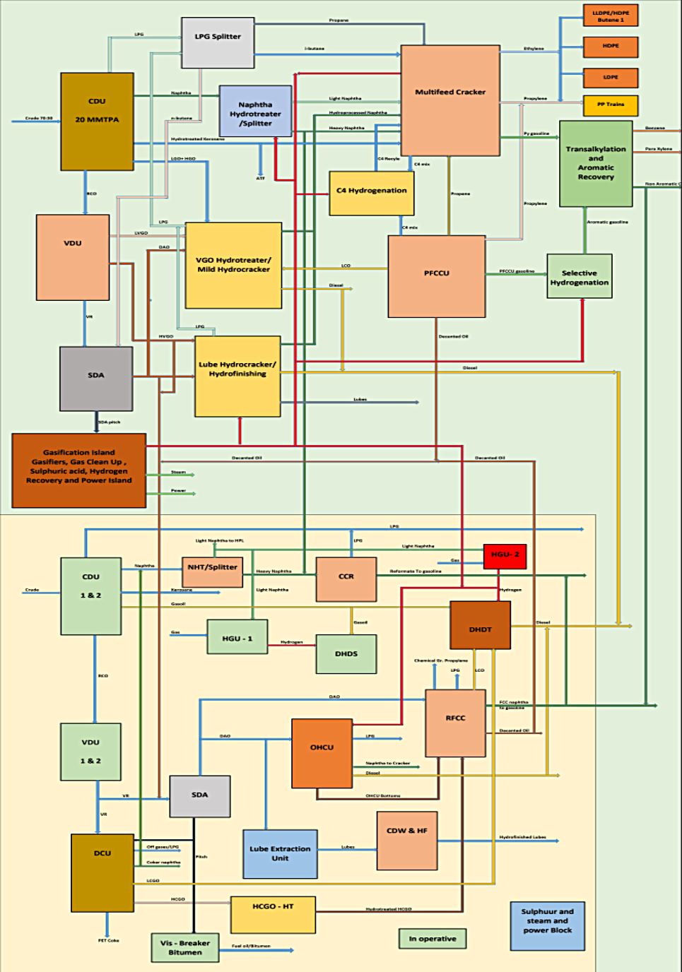
1. A 20 MMTPA Greenfield complex processing a heavy, sour crude slate consisting of 70% Arabian Heavy (AH) and 30% Arabian Light (AL) is foreseen considering API Gravity (Blend): ∼30.5∘ API, Sulfur Content (Blend): ∼2.55 wt%. Because of the 70% Arabian Heavy proportion, the VR yield is substantial, which enables a higher extract of deasphalted oil (DAO) for cracking, while the resulting SDA pitch feeds the Gasification Block to generate synthesis gas (CO+H2) for providing the hydrogen and the steam and power requirements of the complex.
2. Naphtha from CDU provides the core feedstock for the Steam Cracker and Aromatics Complex. About 2.5 MMTPA of naphtha shall be routed to HPL, 500 KTPA of heavy naphtha to the CCR and all the balance Light and Heavy naphtha shall be routed to the New Cracker.
3. Total Kerosene from the Complex is capped at 1 MMTPA and all balance Kerosene is hydrotreated and routed to the new Cracker.
4. The crude recipe provided a significant quantum of the Gas oil Pool, VGO + HVGO + HGO. Capturing deeper vacuum cuts reduces the heavy residue burden, routing a massive stream of paraffinic/naphthenic feeds directly into the hydro-processing and cracking complexes, rather than sending raw heavy molecules to gasification.
5. The VR is sent to the Solvent Deasphalting (SDA) unit, where it is split into Deasphalted Oil (DAO) for further cracking and SDA Pitch, which feeds the Gasification block.
6. The gas-oils from the complex will be disposed as below. 2 MMTPA of LVGO will be sent to existing OHCU. The bottoms of OHCU will be fed to existing RFCC along with Hydrotreated HCGO from existing Coker /CHT. All the balance LVGO will be routed to VGO HDT.
7. The HVGO product in the refinery shall be routed to the new lube block as well as to the Existing solvent extraction lube unit. This will enable production of additional lubes of Type II and III variety through the Hydrocracking and Hydro-finishing route. The existing lube block though based on the solvent extraction route, will provide a wide range and quantity of lubes to be produced to improve the EBITDA of the complex.
8. The naphtha streams from the lube block will be routed to the cracker. The Diesel produced in the block will be routed to the diesel pool. The unprocessed bottoms from the lube block will be recycled back to VGO HDT.
9. The light and the Heavy naphtha from the Hydro-processing block shall be routed to the Cracker. Naphtha from existing OHCU shall also be routed to the new cracker. Kerosene produced from OHCU shall find way into the capped ATF pool. All surplus Kerosene anyway will be routed to Cracker. Diesel from OHCU shall be routed to the diesel product pool, downstream of the new MHC.
10. Hydrotreated Coker naphtha shall be routed to the new Cracker.
11. Off gases from the Existing RFCC and DCU will be routed to the new Cracker for recovery of the ethane and propane for cracking to extinction.
12. All LPG from the existing units CCR, RFCC, OHCU, DCU shall be recovered as commercial LPG. RFCC naphtha shall be routed to the gasoline pool and Light cycle oil will be routed to the existing DHDT. The decanted oil from the RFCC though will be routed to the new Cracker.
13. Disposition of vacuum Residue.
a) The total VR pool will comprise of VR from the vacuum column + Decanted oil from Existing RFCC+ Decanted oil from New PFCCU + Fuel oil from the Steam Cracker.
b) 1.7 MMTPA of VR shall be routed to existing DCU.
c) All the balance VR pool material shall be routed to SDA for separation of DAO and Pitch.
14. New LPG Pool - All the LPG produced from the new facilities comprising of LPG from CDU, LPG from the Hydro-processing facilities such as VGO HDT, MHC, Lube Block shall be processed in an Integrated gas processing facility to separate the Propane, n-Butane and i-butane . The Propane and i-butane shall be routed to the new Cracker. The n- butane shall be used as solvent and for continuous make up in the SDA unit. All the surplus n-butane shall be routed to the new Cracker as well.
15. The existing DHDT shall process the LCGO from the existing Coker and LCO from the existing RFCCU. In case the capacity falls short a part of SR diesel from the new CDU could also be sent to the unit to meet its defined name plate capacity.
16. The high-quality Deasphalted Oil (DAO) recovered at the rate of 65% from the SDA unit is virtually free of nickel, vanadium, and asphaltenes, making it an excellent, highly paraffinic feed for our heavy hydro-processing/Mild HCU block.
17. The SDA pitch provides a high-carbon solid/liquid feed ideally suited for gasification complex.
18.New PFCCU- To maximize high-octane gasoline and propylene generation from heavy fractions, a New PFCCU based on the hydrotreated feed from the new VGO HDT will be installed. Salient features of the unit.
- The unit is designed to high severity to address minimum propylene production of 20%. The propane produced from the unit shall be routed directly to Cracker.
- The Off gases from PFCCU shall be treated and routed to the de-methaniser of the New Cracker for recovery of ethylene and cracking of recovered ethane and propane to extinction.
- C4 mix from the PFCCU shall be mixed with the C4 mix produced in the Cracker , hydrotreated and recycled to Cracker to be cracked to extinction.
- Due to High Severity of operation of PFCCU, the PFCCU naphtha is rich in Aromatics and offers the potential of recovery of the same. This stream to be selectively hydrotreated and combined with the hydrotreated Pyrolysis gasoline from the new Cracker to recover Benzene and PX. A trans-alkylation unit shall be included in the aromatic block to convert Toluene and Mixed Xylenes to Benzene and para Xylene.
- The LCO from the PFCCU will be routed to the new MHC. The Decanted oil from PFCCU will be routed to the VR pool.
19.The New VGO HDT acts as the primary hydrotreating gateway for heavy, cracked, and deasphalted feedstocks, removing sulfur, nitrogen, and metals prior to downstream cracking or conversion. All byproducts and effluent streams exiting this unit, such as sour gas, hydrotreated naphtha and diesel, or segregated LPG feed strictly into the new facility pools. A cracking severity of 15% could be addressed in the VGO HDT.
20.The gasoline pool integration strictly targets Benzene, Paraxylene (PX), and Non-aromatics, with zero production of toluene and mixed xylenes.
21.New Mild Hydro-cracker- The unit processes the combined heavy stream of VGO and PFCCU LCO. The unit is designed for high severity up to 60% to minimize the total diesel production from the complex. This is the key as distillates vis a vis petrochemicals adversely impact the EBITDA of the complex. The high severity of the unit enables a lot of light ends such as LPG and naphtha which find way into the Cracker.
22.Upgrading our hydro-cracking strategy for the MHC to Full-Conversion Recycling a full-conversion hydrocracker cracks heavy molecules into prime steam-cracker naphtha and LPG. Also the HGO from the CDU unit could be diverted to VGO HYDT rather than being routed to MHC. This will enable further reduction of total diesel.
23. Petrochemical Orientation- The Petro FCC and the multi-feed Cracker with Zero LPG from the new facilities provides a huge opportunity to maximize the petrochemical intermediates. Also the Integration of Aromatic Rich gasoline from the PFCCU with the pyrolysis gasoline from Cracker provides an opportunity to maximize recovery of Aromatics. All C4 mix streams from Cracker and PFCCU shall be also hydrotreated and recycled for cracking to extinction.
24. The cracker design accommodates both liquid naphtha cracking and dedicated gas/LPG cracking, allowing real-time optimization on seasonal feed-stock pricing and product demand of ethylene and propylene. All internal refinery byproducts—including hydro-processed naphtha, kerosene, PFCCU and DCU light ends, and fractionated butanes—are fully utilized within the complex, achieving zero-waste light hydrocarbon valorization. Chemical grade propylene from Existing PFCCU will also be routed to Cracker for production of Polymer grade propylene. Hydrotreated DCU naphtha as well as OHCU naphtha and Kerosene is also intended to be routed to the Cracker.
25. VHP steam requirements: In general Cracker and PFCCU major compressors will be driven by VHP ( 125 bar, 540 Deg C) steam. The Cracker invariably produces its own VHP steam and in normal operation does not require to import VHP steam. PFCCU also produces a lot of HP steam. However, since the major compressors viz the Main Air Blower and WGC are major drives. To optimize the overall steam requirements it is advisable to run these major compressors with VHP steam driven extraction cum condensing turbines. This will imply a lot of import of VHP steam from the CPP and corresponding export of HP steam from from the unit to the main HP steam header.
26. The PFCCU is a large unit and the Regenerator overhead will offer the potential of recovery of lot of green power from the system. An overhead expander will be equipped in the system to recover power and align it with the main power system of the complex. This will enable rationalization of the overall power system and provide a lot of spare capacity in the electrical system.
27. For sizing of the Gasification island the following major requirements are to be catered to as a minimum.
- High purity Hydrogen 170 KTPA
- VHP Steam ( 125 bar 540 Deg C) 300 TPH
- MP steam ( 14 bar) 100 TPH
- LP steam including Pegging steam 150 TPH
- Net Power 350 MW
28. Downstream Block of the complex can be simplified and restricted only to polymers. For Polyethylenes LLDPE/HDPE, HDPE, LDPE and Butene 1. All the propylene and some ethylene shall be converted to random, Co and Impact PP. A common warehouse with vertically automated system shall be considered in the plant to optimize the plot requirements. In addition to the above considerable quantity of Benzene and Paraxylene is also produced in the complex.
29. A rationalized distillate fuel pool of gasoline, ATF and Diesel, commercial LPG restricted to the existing refinery units, maximized lubes and petrochemicals enhance the revenue realization from the complex considerably. This improves the EBITDA substantially.
Gasification Island
1. The Pitch from the Solvent Deasphalting unit will form the feed to the gasifier. The gasifier could be based on High-pressure entrained-flow such as Shell/ConocoPhillips or equivalent heavy residue configuration. The gasifier would operate at 40–80 bar and >1,400 deg C. A 2+1configuration is proposed to be considered for the gasification system.
2. Raw syngas (CO+H2) produced in the gasifier shall be routed to water gas shift (WGS), acid gas removal (AGR), and Pressure Swing Adsorption (PSA) to yield the 170 KTPA makeup hydrogen required by the complex.
3. An Air Separation unit ( 1+1) shall be installed in the gasification island to supply high-purity oxygen (99.5% O2) for the entrained-flow gasifiers. Typically 0.85 - 0.9 tons of O2 per ton of pitch will be required.
4. High-temperature raw syngas exiting the gasifiers (>1,350 deg C) is quenched and cooled via radiant and convective syngas coolers, generating ultra-high-pressure superheated steam. About 2.2 tons of VHP steam per ton of pitch is produced which supplements the VHP pool of the complex.
5. Considerable amount of steam would be required to produce 350 MW of power and also extract the MP and LP steam from the STGs. Large boilers arranged in the capacity range of 500 TPH in 3+1 configuration close coupled to 3+1 STGs each of 125 MW capacity could be installed to meet the steam and power requirements of the complex including the captive requirements of the gasification island.
6. SDA pitch contains 4-4.5% sulfur, generating 6 - 6.5 TPH of H2S in the raw syngas. Acid gases recovered in the Acid Gas Removal (AGR) unit are routed to a Wet Sulphuric Acid (WSA) polishing plant. Considerable amount of sulphuric acid and HP steam can be generated in the process.
7. After hydrogen extraction and acid gas removal (H2S/CO2 separation), the balance of clean syngas is first routed to the auxiliary burners of the CPP boilers.
8. Any portion of syngas not required for boiler firing can be directed to a chemical synthesis loop and Ammonia could be produced Utilizing secondary nitrogen from the ASU and shifting remaining CO/H2 yields a potential ammonia production capacity can be created. Reacting the synthesized ammonia with high-purity CO2 recovered from the AGR unit yields potential urea production. This can be very useful .
9. The conversion of recovered acid gases through sulfur burning, catalytic oxidation (SO2→SO3), and absorption is highly exothermic. Recovering this reaction heat via waste heat boilers generates High-Pressure (HP) steam at 40 bar/400 deg C, which feeds into the complex intermediate pressure/HP steam header network.
10. Because of the steam generation and the hydrogen recovery requirements of the gasification island 100% of the balance syngas is consumed in the system and there is no surplus gas available for production of Ammonia/Urea.
11. Since the proposal involves both retaining the existing conversion facilities as well as create new green field facilities split in a couple of different adjoining locations, the total capex for the Project would be to the tune of $ 12-13 billion based on the hybrid mode of implementation. The addition of the Steam Cracker and massive PE/PP units establishes the complex as a top-tier petrochemical integration hub while the new Lube Unit diversifies the high-margin product slate.
12. A world-scale 20 MMTPA integrated refinery coupled with a massive petrochemical block with over 6-7 million tons of value add commands a blended net margin well above standalone refining due to high-value chemical derivative upgrading. Returns upwards of 16-18% are anticipated. The strong post-tax IRR and short payback period stem from the high-margin product slate of the integrated complex—leveraging deep conversion refining, paraxylene/benzene aromatics, a steam cracker, and massive polyethylene/polypropylene derivative blocks to capture maximum delta above crude feedstock costs.
Figure 2 - Proposed Configuration for the Integrated Haldia Refining Complex
Major Project Risks
- Crude prices. Anything above $75/barrel will impact the economics adversely.
- Availability of land and a strategy to optimize the layout. Sequential removal of Crude and product tanks from the Existing Refinery to a virgin area and the schedule implication, shutdown are critical areas to be planned and phased out.
- Due to split geographical locations additional connectivity and integration costs would have to be contended with . This will enforce implementation and operational risks.
- The common gas plants for the Hydro-processing block will help rationalize plot space and the number of equipment in the plant. This may force integration and turn-down risks. Common hydrogen compression systems would be foreseen in the plant. Operational risks will be mitigated through a sparing philosophy. Common recycle gas compressor is foreseen for VGO HDT and MHC.
- The Gasification Block is the critical block. To ensure sustained operation the ASU, gasifiers and he Hydrogen trains recovery systems will be built in trains. The gasifiers will be spared. Similarly in the steam and power generation facilities adequate capacity and spares shall be incorporated in the design.
- Water systems designs will be carried out on lines of Zero discharge. All treated waste water, cooling tower blow downs, boiler blowdowns shall be treated and recycled through a multi-chain high recovery system to produce DM and Raw water to minimize the makeup. Fresh water shall be recovered through a river water based desalination system. A segregated cooling water system shall be followed in the complex.
Conclusion
Most of the old projects in the country require a concerted strategy to avail the advantage of the existing presence and the changing requirement trends. Various plants need to be revisited to devise a strategy to expand, modernize and evolve them into large state of the art petrochemical complexes. This perhaps will be the need of the hour to cater to the changing requirements and operational dynamics of the country!