Setting up a Grassroots Complex Maximizing Advanced Petrochemicals Dhamra- India - Part III

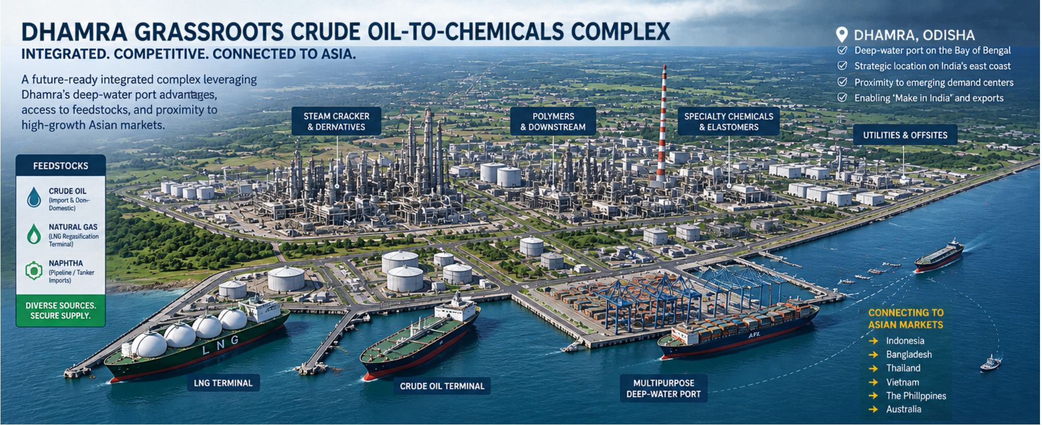
This is in continuation of Part I and Part II of this article series and deals with the core Complex Configuration wherein the emphasis is essentially on developing the building blocks for the downstream petrochemicals.
Marine Infrastructure and Feedstock Management
Dhamra is recognized as one of India's deepest ports on the east coast, specifically designed to accommodate super cape-size vessels and large gas carriers. The channel and berthing basins typically maintain natural and dredged drafts exceeding 15 to 18 meters, allowing fully loaded VLCCs-Very Large Crude Carriers to berth safely without major tidal restrictions. For handling very large liquid hydrocarbon carriers outside the restricted basin channels, SPM systems will have to be typically positioned several kilometers offshore to ensure safe draft clearance. Sub-sea and on-land pipelines will connect these offshore moorings directly to onshore tank farm storage area.
Siting a 20 MMTPA integrated refinery cum petrochemical complex requires substantial contiguous land parcel—typically in the range of 2,500 to 3,500 acres depending on configuration of process units, tank farms, effluent treatment plants, and safety buffer zones. To safely service a 20 MMTPA integrated complex without bottle-necking maritime logistics, the marine offloading and export architecture requires deep-water positioning beyond the coastal shallow sandbars about 5 to 8 kilometers offshore in natural water depths exceeding 22 to 25 meters. This depth accommodates Fully Loaded Very Large Crude Carriers up to 300,000 DWT processing the sweet/sour crude slate. The two crude SPMs could be spaced a few kilometers apart to allow simultaneous, independent mooring and safe swing circles for massive tankers. Sub-sea crude pipelines of 48” line sizes could trench from these buoys directly to the onshore tank farm base.
Dedicated Deep-Water Jetty
A Dedicated Deep Water Jetty would be necessary for evacuation of smaller parcel of products and Petrochemicals, and could be located within the protected harbor basin maintained at a dredged depth of 15 to 16 meters. The Jetty could be equipped with multi-product arms for handling chemical and hydrocarbons and containerized polymer shipments feeding regional markets. The product SPMs could be linked via dedicated product export lines running parallel to main pipe-rack corridor entering the terminal's marine loading arms.
Crude Recipe for the Complex
To maximize residue yield for the SDA gasifier, while controlling metals like Vanadium/Nickel and maintaining good straight-run middle distillate yields a 60:40 or a 70:30 sour: sweet crude recipe could be considered. With a 60:40 slate Solvent Deasphalting using a C4/C5 blend solvent yields 60-65% DAO and 40-35% Pitch. The pitch concentrates the heavy asphaltenes, sulfur, and heavy metals like Vanadium and Nickel making it an ideal, low-cost gasification feed-stock. By converting bottom-of-the-barrel into syngas via SDA + Gasification the bottoms upgradation facilities get rationalized. The high-sulfur syngas stream from POX unit yields significant volumes of concentrated H2S, which could feed the Claus Acid Gas Removal unit to supply sulfuric acid or elemental sulfur for industrial use.
The 70:30 Sour : Sweet increases the heavy/sour fraction. The financial and operational implications of this shift center on price differentials, capital expenditure, operating expenses, and overall plant economics. Medium-to-heavy sour crudes historically trade at a discount compared to light sweet benchmarks due to higher sulfur content, higher metal counts, and a larger heavy-ends yield tail. According to market trends the price spread between light sweet and medium/heavy sour crudes generally averaged $2.50 to $4.50 per barrel. Overall running a 70:30 sour : sweet ratio lowers total complex raw material costs by $200 to $280 Million annually which is substantial. Increased residue on account of the sourer crude will increase the acid gas generation while increasing the overall syn gas generation by 12-15% to support the production of Hydrogen, Power and Steam for the complex. The heavier and sourer crudes though would directionally reduce the total SR naphtha by about 1-1.5% ,which of course, would be a feedstock penalty for the conversion units. This does impact savings which accrue on account of feedstock cost savings.
It may be worthy of notice though, that while crude purchasing costs decrease with a 70:30 sour slate, processing costs increase across several units as High-sour slates contain elevated chlorides and naphthenic acids/sulfur, requiring 2-stage or 3-stage high-efficiency desalter units and upgraded column metallurgy to SS-316L / Duplex / Monel cladding in CDU tower overheads. The Acid Gas Removal and Claus SRU capacity will expand by ~15–18% to process the extra H2S. The POX gasification unit scales up due to increased pitch processing at the cost of increased gasification block Capex. The 70:30 slate generates higher DAO for hydrotreater facilities, which expands cracking throughput for high-margin petrochemical propylene, naphtha and BS-VI diesel. The additional SDA pitch gasified generates incremental syn gas eliminating the need to import merchant power or natural gas for hydrogen reforming. In view of the above 70:30 Sour : Sweet blend is significantly more cost-effective, as the crude discount savings combined with increased captive syngas/power generation from the larger SDA pitch stream, far outweighs the incremental upfront metallurgy and SRU Capex.
For the purposes of study the following 70:30 Sour : Sweet crude assay, operating parameters, and atmospheric distillation unit yield profile scaled for a 20.0 MMTPA grassroots complex is considered as follows: Composite API Gravity: ≈30.5, Total Sulfur Content: ≈1.95 wt% ,Total Acid Number (TAN): ≈0.15 to 0.25 mg KOH/g, Conradson Carbon Residue (CCR): ≈5.8 wt%, Vacuum Residue Potential (538∘C+): ≈24 wt%.
The typical yields from CDU would be 3.5% of LPG + fuel gases, total naphtha about 14%, kerosene about 12.5%, light gas oil about 12.5% and heavy gas oil about 8.2% with the balance 44.5% of atmospheric residue. Due to higher bottoms, it requires a large-capacity Vacuum Distillation Unit (VDU) to pull Vacuum Gas Oil (VGO) from the column as feed to the secondary processing facilities. leaving Vacuum Residue (VR) as feed to the bottoms upgradation units. The VR goes straight into the Solvent Deasphalting (SDA) unit, yielding 60-65% Deasphalted Oil for Hydrotreater and 40-35% heavy asphaltic pitch to feed POX gasifier for hydrogen, steam, power, and ammonia production.
A single-train Crude Distillation Unit (CDU) and Vacuum Distillation Unit (VDU) to process 20.0 MMTPA of 70:30 Sour : Sweet crude slate requires heavy-duty column sizing, robust furnace duty, and high-vacuum jet ejector systems. A single-train configuration of this scale is within modern mega-refinery execution limits, reducing plot footprint, piping interconnections, and rotating equipment count. To process the generated Atmospheric Residue in a single vacuum column train, the unit must be designed with deep-vacuum capabilities and high thermal efficiency. To handle massive vapor and liquid volumetric loads of residue feed, the main vacuum tower requires an inner shell diameter of 11.5 to 13.0 meters, utilizing high-efficiency structured packing in flash and wash zones to minimize pressure drop. Flash zone pressure may be maintained via a multi-stage steam ejector system coupled with surface condensers. The metallurgy in the plant may be ASTM A240 Type 316L / Alloy 825 cladding in flash zone, wash section trays, and overhead condenser systems to combat naphthenic acid and high-temperature sulfur corrosion.
VGO from VDU is routed entirely to VGO Hydrotreater to maximize production of petrochemical cracker feed, naphtha and middle distillates. The vacuum residue from VDU is routed to Solvent Deasphalting (SDA) unit using a C4/C5 paraffinic solvent. The Deasphalted Oil is sent to the Hydrotreater. The Asphaltic Pitch (40-35% bottom) is fed directly into the Partial Oxidation (POX) Gasifier to generate the complex's entire requirement of hydrogen, high-pressure steam, power, and ammonia synthesis gas. Sizing the Solvent Deasphalting unit for the 70:30 Sour : Sweet crude configuration provides a clean mass and energy integration link between the refining column bottoms and the downstream Partial Oxidation (POX) Gasifier block.
SDA Unit Configuration
A C4/C5 solvent mixture achieves a high 65% liquid volumetric/mass yield of Deasphalted Oil while selectively rejecting 35% as heavy asphaltic pitch containing the majority of the feed metals (V,Ni), CCR, and asphaltenes. To process heavy vacuum residue in an integrated complex, the unit requires 2 parallel extraction trains to manage liquid-liquid contacting stability and high internal liquid hold-up. The contactors would be equipped with High-duty baffle tray/packing and to minimize fired heater duty and utility steam, the unit may utilize a supercritical solvent recovery system. The C4/C5 solvent is separated from the DAO stream at supercritical conditions, saving 30–40% in cooling water and heat duties compared to conventional sub-critical flash designs. The Solvent-to-Oil Ratio is maintained between 4.5:1 to 6.0:1 to guarantee high phase-separation sharpness. The molten SDA pitch may be routed directly to a Partial Oxidation (POX) Gasification unit. The gasifier design completely satisfies the hydrogen requirements of the hydro-processing demand of the Naphtha Hydrotreater, Kerosene Hydrotreater, Diesel Hydrotreater, and Mild Hydrocracker across the complex. Additionally, the Gasification island shall supply total steam and power requirement of complex from the power island.
SDA Recovery (65%→60%)
In a 20 MMTPA complex processing about 4.5 MMTPA of Vacuum Residue (VR) through SDA unit, dropping DAO recovery by 5% increases the solid/heavy pitch yield from 35% to 40% of VR feed. This would yield incremental pitch to deliver additional clean thermal energy directly to utility and gasification island. This strategy introduces two key metallurgical and operational shifts. Higher Asphaltene & Metal Loading in POX Gasifiers - By cutting deeper into the heavy ends and leaving more asphaltenes, nickel, vanadium, and sulfur in SDA pitch, the feedstock viscosity and ash content would rise slightly. The POX gasification burners and down-stream slag removal systems would be rated for higher metals and particulate loading, but since POX is inherently designed for heavy ash-bearing residues this should not be an issue. Quality of Deasphalted Oil to Hydrotreaters PFCCU - Extracting less DAO (60% recovery instead of 65% cut) means the recovered DAO is slightly heavier and contains higher CCR and metals. The hydro-processing units must have adequate catalyst demetallization and hydrotreating capacity to absorb slightly heavier DAO feeds. Dropping SDA recovery to 60% monetizes internal residue upgrading limits, boosts captive syngas/pitch fuel generation, and keeps the complex completely self-reliant without relying on grid power imports or expensive imported gas. By adjusting SDA recovery down to 60%, one is able to capture marginal heavy ends into the pitch pool—generating incremental thermal energy needed to make gasification and utility island 100% self-sufficient with zero power or gas imports.
Disposition of streams from CDU
Light Naphtha is combined as NHT feed, hydrotreated, and routed to Steam Cracker. Heavy Naphtha is hydrotreated in NHT along with LN. About 1.5 MMTPA of SRN will be routed to CCR for maximizing the production of Aromatics i.e. benzene and PX with balance HN routed to Cracker. Of the total SR kerosene produced from the unit, 1.2 MMTPA after Merox shall be routed to ATF pool. Balance Kerosene shall be hydrotreated and routed to Steam Cracker. The Light gas oil from CDU shall be routed to Mild Hydrocracker and Heavy gas Oil shall be routed to VGO hydrotreater. All LPG from CDU , VGO hydrotreater, Mild Hydrocracker is centrally pooled and routed to LPG splitter to recover Propane, n- butane, i - butane. The propane and i- butane is routed to steam Cracker and n-butane is routed to Solvent Deashpalting Unit as solvent.
VGO Hydrotreater
Configuring VGO Hydrotreater to process the combined heavy liquid feed pool—comprising of Straight-Run HGO, VGO, and Deasphalted Oil—at a mild cracking severity of 15% prepares a highly reactive, hydrotreated feedstock for downstream Petrochemical Fluid Catalytic Cracking Unit (PFCCU). Pure H2 is supplied directly from POX Gasification unit to saturate aromatics, remove sulfur & nitrogen, and partially hydro-demetallize the DAO fraction. At 15% conversion, the feed is transformed into light gaseous products, cracked naphtha, LPG, and a bulk hydrotreated heavy product stream. Routing DAO through VGO HT successfully removes residual metals (V, Ni) and CCR down to trace levels, preventing rapid coking and catalyst poisoning in downstream PFCCU. The 15% conversion severity generates LPG and hydrotreated naphtha, which feeds directly as Ethylene Steam Cracker feedstock. The hydrotreated heavy feed boasts significantly reduced aromatic ring count and lowered sulfur/nitrogen levels, setting up PFCCU to operate at high severity for maximum propylene and ethylene yields.
Petrochemical Fluid Catalytic Cracking Unit (PFCCU)
The decanted oil from PFCCU and fuel oil from steam cracker will be routed to VR pool. SDA capacity will be correspondingly higher and so will the DAO and Pitch. Recycling heavy byproducts—specifically the Decanted Oil / Slurry Oil from the Petrochemical FCCU and the Pyrolysis Fuel Oil from Ethylene Steam Cracker—back into Vacuum Residue pool closes the heavy-ends loop entirely. This eliminates heavy fuel oil export products and converts them into high-value petrochemical feed and syngas. By routing PFCCU decanted oil and Cracker PFO back to SDA unit, the complex produces zero low-value heavy fuel oil, converting 100% of the barrel into clean gases, distillates, and petrochemical precursors. The hydro-treated heavy feed to PFCCU increases driving higher high-value olefin yields.
PFCCU will be high severity with minimum 20% production of Propylene with PFCCU capacity being iterative as LCO is routed to MHC along with LGO and utilize 40% cracking in MHC. To minimize diesel produce, a part of heavier diesel from MHC will be routed to PFCCU. Configuring a high-severity Petrochemical Fluid Catalytic Cracking Unit operating on hydro-treated heavy feed from VGO Hydro-treater is the central Olefin engine of the complex. Operating at high severity—characterized by elevated riser outlet temperatures (540∘C−560∘C), high catalyst-to-oil ratios, and specialized ZSM-5 shape-selective zeolitic additives—shifts the yield envelope away from conventional transportation fuels towards Propylene and Ethylene, and aromatic-rich naphtha. PFCCU maximizes propylene and directly anchors a world-scale downstream block. Ethylene is recovered in the gas plant and routed to the Ethylene Derivative complex while the C4 Stream provides abundant feed for recovery of Butadiene.
Mild Hydrocracker
For minimizing finished diesel while creating a tight recycle loop between MHC and PFCCU. Operates at 40% net hydro-cracking conversion to convert aromatic LCO and heavy gas oil cuts into naphtha and light distillates. Rather than routing un-cracked 60% heavy diesel fraction entirely to BS-VI commercial diesel pool, a calculated portion of hydrotreated diesel can be recirculated back to PFCCU feed. This further minimizes final diesel output while increasing PFCCU feed throughput, driving propylene production.
- MHC Hydrocracked Naphtha: Highly paraffinic hydrocracked naphtha cut is ideal as Ethylene Steam Cracker liquid feed pool. Part of diesel may be exported as ultra-low sulfur diesel. A portion of this hydrotreated heavy diesel stream may be recycled back as PFCCU feed to minimize commercial diesel production and expand PFCCU feed throughput, driving total propylene production higher. MHC LPG is routed directly to Central Saturated LPG Pool.
- MHC Hydrocracked Naphtha + Light Distillates/Kerosene : Routed directly to Steam Cracker Liquid Feed Pool.
- Recycle to PFCCU: 40% routed back as a high-quality co-feed to the high-severity PFCCU. Balance 60% routed to BS-VI finished diesel pool. The Propylene Generation reaches impressive world-scale feedstock for derivative polypropylene and specialty chemicals. Off gases from PFCCU is routed to Demethanizer of steam cracker to recover residual ethane and propane for cracking to extinction. Ethylene from PFCCU will also go to DM for product recovery. Propane from PFCCU will be routed to Steam Cracker while Butanes is routed to central LPG pool. PFCCU naphtha will be routed to Aromatic complex downstream of CCR for recovery of Benzene and PX, zero Toluene and Ortho and meta Xylenes. Hydro-treated Py-gas from cracker will also be routed to Aromatic complex for Benzene and PX recovery.
- Simultaneously, recycling the Mild Hydrocracker unconverted bottoms back to RFCCU feed preserves the paraffinic/naphthenic cat-cracker feed quality, locking in high conversion rates and protecting valuable ethylene and propylene yields without increasing crude intake.
PFCCU configuration
Configuring Petrochemical PFCCU block as two parallel Reactor-Regenerator (R-R) trains, each equipped with dedicated Main Air Blowers and Wet Gas Compressors, feeding into a common Product Main Fractionator represents an optimal configuration for a mega-scale complex.
- Splitting large PFCCU into two trains, ensures high turndown flexibility, manageable regenerator air/heat balances, and prevents a total complex shutdown during catalyst change-outs or maintenance.
- Dedicated Main Air Blowers & Flue Gas Systems — requires distinct combustion air rates and catalyst regeneration heat management. Independent MAB trains ensure precise control over catalyst coke burn-off and regenerator temperature without pressure cross-talk. For Wet Gas Compressors (WGC) while a common header can be designed, assigning dedicated centrifugal WGC trains to each reaction train prevents complex back-pressure anomalies and allows seamless single-train operation if one R-R circuit undergoes statutory inspection.
- Common Product Main Fractionator Energy Optimization is fully viable and eliminates duplicate heavy distillation columns, reducing plot space and piping interconnections Optimizes high-level heat integration in reboilers, pump-arounds, steam generation into a single unified utility network. The common fractionator must be sized to handle the combined vapor and liquid loads of both trains, resulting in a large column diameter, potentially 9 to 11 meters, utilizing high-efficiency structured packing in the flash zone and heavy wash sections.
- Independent heavy oil quench systems must be installed immediately downstream of each reactor vapor outlet. This locks the cracking reactions instantly and prevents coking in the transfer lines before the vapors enter the common fractionator inlet header.
- Each R-R train must retain independent blowdown and emergency shutdown isolation valves to flare, ensuring that an upset in Train A does not compromise the mechanical integrity or safety envelope of Train B or the shared fractionator.
Steam Cracker
The unit is a multi-feed Cracker with both liquid and gaseous feedstock. The Liquid Feed Pool (C5+)comprises of SR Naphtha, VGO HDT Naphtha, surplus Kerosene, MHC Naphtha & Light Distillates, where as the Saturated Gas Feed Pool comprising of PFCCU Propane, LPG Propane, Iso-Butane, and surplus Normal Butane. C4 loop by combining the cracking and catalytic olefin streams, extracting polymer-grade 1,3-Butadiene, and hydrotreating the balance for cracker recycle completes the heavy and intermediate gas integration across the complex.
Crude Butadiene / C4 Mix comprises of Butadiene and PFCCU Butylenes Mix (C4 isomers). Using extractive distillation with NMP or DMF solvent, the mixed C4 stream is processed to extract high-purity 1,3-Butadiene. The balance C4 stream after extraction of butadiene passes through a Selective Hydrogenation Unit to convert trace acetylenes and diolefins into mono-olefins/paraffins, protecting downstream equipment and burner nozzles. The hydrotreated C4 mix is routed directly back into the Ethylene Steam Cracker gas/liquid cracking furnaces as a clean cracking co-feed. Since a large quantum of 1,3-Butadiene is required and is targeted for 750 KTPA additional C4 olefin capacity across the complex will be required. Ethylene Steam Crackers running on mixed liquid/gas feeds yield high 1,3-butadiene concentration, but PFCCUs produce predominantly mono-olefins (1-butene, 2-butenes, and i-butene) rather than diolefins (1,3-butadiene). Because the PFCCU generates a massive C4 stream that is rich in n-butenes and i-butene, but low in 1,3-butadiene, the most elegant solution is to integrate an On-Purpose Butadiene Generation Block utilizing Oxidative Dehydrogenation (ODH) or Dehydrogenation (DH) technology on abundant C4 raffinate.
Olefin Pool - Cracker + High-Severity PFCCU
The combined outputs of steam cracker along with high-severity PFCCU production establishes the complex's final master olefin inventory. Total Ethylene Production from the complex is expected from 2,900 KTPA and total propylene production is expected to be around 2,930 KTPA. The capacity parameters of Ethylene Steam Cracker Furnaces, excluding Ethylene recovered directly from high-severity PFCCU contributes to pool. Cracker would be processing furnace Feed of 7,700 KTPA with liquid feed 5,700 KTPA and balance as gaseous feedstock including C4 recycle.
- Furnace Configuration comprises of 10 to 12 mega-cracking furnaces, typically 9–10 operating + 1–2 in decoking mode. Liquid Furnaces 7–8 furnaces operating at high Coil Outlet Temperature and Gas Furnaces (C3/C4 & Recycles) with 3–4 dedicated gas-cracking furnaces. Downstream Recovery Section shall comprise of a single-train, world-scale cold box and fractionation unit rated for higher capacity to include the recovery of the Off gases from PFCCU. For heavy liquid and mixed-feed cracker designs, the industry standard for large-capacity units is a Twin-Cell Cracking Furnace pioneered by licensors like Technip Energies (GK6/Radi-Fire), Linde (Pyrotol), Lummus (SRT-VI/VII), and Wison. Maximum World-Scale Single Twin-Cell Furnace Capacity of 200 KTPA to 250 KTPA of Ethylene output per furnace. The Heat Duty of 110 – 130 MW per furnace is anticipated with Coil Pass Configuration of 8 to 12 parallel radiant coil passes per cell downstream of which Transfer Line Exchangers (TLEs) are located.
- A single Cracked Gas Compressor in a single train is envisaged. Leading compressor OEMs, such as Mitsubishi Heavy Industries (MHI), Elliott Group, Siemens Energy, and BHGE manufacture single-train CGC systems capable of handling ethylene capacities up to 3.0 – 3.2 MMTPA. A 5-stage compression system housed across 3 casings, Low Pressure, Medium Pressure, High Pressure on a single shaft, driven by an extraction-condensing steam turbine (~90–110 MW rating).
- PFCC off-gas exits PFCC Gas Concentration / Unsaturated Gas Plant at 9–10 bar(g). The gas passes through dedicated acid-gas removal, H2S/CO2 scrubbers, and catalytic reactors, to remove trace O2, NOx, and Arsine. A Dedicated Off-Gas Compressor to boost pressure to ~30–35 bar, uses a much smaller 2-stage compressor, rather than burdening the main cracker CGC. The pre-purified, dried gas feeds directly into the Demethanizer chilling train at its pressure level. PFCC off-gas contains trace contaminants (Arsine, Phosphine, Carbon Monoxide, Oxygen, NOx, Diene traces) that can poison precious-metal hydrogenation catalysts in the cracker acetylene converter. Purifying this stream separately isolates risks from the main furnace cracking loop.
- Both the Ethylene and Propylene Splitter towers can be constructed as single-shell vertical columns using Heat Pump systems and high-capacity Mass Transfer MD trays. Using Heat Pump technology allows the column to operate at ~9–11 bar(g) instead of 18–20 bar(g). Lower operating pressure expands the relative volatility between propylene and propane, reducing the total theoretical stage requirement significantly. High-capacity Multi-Downcomer MD trays increase active bubbling area by up to 30–40% compared to standard 4-pass crossflow trays, preventing liquid flooding under heavy internal reflux ratios. The column diameter is expected to be about 8-9 meters and height about 105 – 115 meters tangent-to-tangent. Operating Ethane-Ethylene Splitter with an Open-Loop Heat Pump, using Ethylene overhead vapor as the refrigeration medium, enables single-shell construction. Lower column pressure (~8–10 bar (g)) increases relative volatility, reducing required stages. High-Capacity MD Trays or high-efficiency structured packing in the upper rectifying section is used to minimize pressure drop per stage. The estimated Single Column Diameter is expected between 6- 7 meters with 85 – 95 meters height.
On-Purpose Butadiene via Oxidative Dehydrogenation
Instead of recycling the post-extraction C4 raffinate directly back to the steam cracker furnaces, route a major portion of it through an Oxidative Dehydrogenation unit e.g., Houdry Catadiene, BASF/Linde, or Oxo-D process In Oxidative Dehydrogenation Reaction n-butenes react selectively with oxygen over a bismuth-molybdate catalyst at low pressure to yield 1,3-butadiene and water. At ∼75%nbsp;single-pass conversion processing n-butenes generates additional 1,3-Butadiene. With this the Target of 750 KTPA of 1,3-Butadiene for synthetic rubbers (SBR, PBR) and ABS plants without altering the upstream CDU/VDU or cracking severities. The ODH process is highly exothermic, generating valuable high-pressure steam that can be integrated into the complex energy header. Unlike conventional direct de-hydrogenation, which is endothermic, highly energy-intensive, and catalyst-coking prone, Oxidative Dehydrogenation reacts n-butenes with oxygen in the presence of steam over a specialized metal-oxide catalyst. The formation of water drives the reaction forward at high single-pass conversions (≥75%) at moderate temperatures of 350∘C−450∘C. Oxygen continuously burns off carbonaceous precursors, maintaining long catalyst cycle life without frequent decoking shutdowns. Steam serves as a heat sink, diluent to prevent explosive air-hydrocarbon mixtures, and promoter to maximize 1,3-butadiene selectivity (gt;75%−85%).
BDH Operates with fixed-bed tubular reactors, typically 2 or 3 parallel trains for a 500+ KTPA unit. The reactors are shell-and-tube exchangers packed with bismuth-molybdate catalyst, cooled by circulating molten salt or generating high-pressure steam. The Separation & Recovery Train consists of a Quench Tower, a degasser, an Oxygen Stripper, and a direct Solvent Extractive Distillation column. Several leading international technology providers license commercial ODH technology such as TPC Group (Houston, Texas, USA) Operates multiple world-scale OXO-D™ units producing on-purpose butadiene from refinery/cracker C4streams. Sinopec / PetroChina Facilities ODH units process FCC and steam cracker C4 raffinates. Formosa Petrochemical (Mailiao, Taiwan) Operates on-purpose C4 dehydrogenation to supplement butadiene extraction for ABS and SBR monomer plants.
Aromatics Complex - Benzene - Para-Xylene
The Feed to the unit comprises of Hydrotreated Heavy Naphtha via High-Severity CCR Reformer, PFCC Naphtha and Hydrotreated Pyrolysis Gasoline from Cracker for Maximization of Benzene and Para-Xylene with total internal isomerization / dis-proportionation of Toluene, Ortho-Xylene, and Meta-Xylene. Inside the Aromatics Complex, feed passes through Naphtha Splitter, Sulfolane Extraction unit, Toluene Disproportionation / Transalkylation (TATORAY) unit, and Parex/Isomar Xylene separation loops to deliver 1075 KTPA Benzene, 2110 KTPA Para Xylene, 2250 KTPA Balance. All produced Toluene is routed to Tatoray transalkylation reactor, where it is reacted with heavy aromatics (C9/C10) over a noble-metal zeolite catalyst to produce an equimolar blend of Benzene and Xylenes. Standard xylene splitters isolate Para-Xylene, Ortho-Xylene, and Meta-Xylene. By eliminating Ortho Xylene recovery, the entire mixed-xylene stream is routed through Isomerization (Isomar) unit to re-establish thermodynamic equilibrium (~24%PX), followed by continuous multi-pass separation in the Parex adsorption unit to maximize Para-Xylene yield. The 1.2 MMTPA Styrene plant requires 945 KTPA of Benzene. With total Benzene output now at 1,075 KTPA, the balance benzene is routed to Phenol and Acetone plant. Total PX output is significant and and an important feedstock for polyester and PET manufacturing. PX can be converted to PTA.
Hydrogen balance
The complex generates significant quantities of byproduct hydrogen from catalytic reforming, steam cracking, and Styrene units. It is anticipated that the following quantities be produced CCR reformer 45 KTPA, Steam Cracker 85 KTPA, EB Dehydrogenation 23 KTPA. The Total Hydrogen requirement anticipated is Hydro-processing Block 175 KTPA, PGH 30 KTPA, SHU 12 KTPA.
Mechanical Transport Considerations
Two C3 splitters with weights between 1800-2000 Metric Tons. Delivering the columns directly via the Dhamra Port jetty and using heavy self-propelled modular transporters (SPMTs) to move it to the plot plan is logistically ideal and bypasses inland road transport constraints. Using a tight 450 mm tray spacing with MD trays fits the stages within a single shell without exceeding structural wind-load deflection tolerances.
Vessels with diameters >6.5 m generally are supplied to site in multiple pieces or in knocked down condition. However, for a deep-water port like Dhamra Terminal, large sub-assemblies / single piece equipment can be barged directly to the site. Field erecting large diameter regenerator/reactor shell is standard practice across Indian mega-projects. Heavy lifting ring cranes with capacities more than 3,000-ton can handle these equipment/ subsections. It is expected that the diameter of the equipment will be such that it would allow uniform pipe-grid or domed-grid air distribution without localized dead zones or severe gas-channeling issues that plague oversized vessels (>18−20 m).
Gasification Island
SDA Heavy Pitch is the primary heavy liquid feed to multi train Partial Oxidation (POX) gasifiers operating at 65 bar. The syn gas produced in the gasifiers is treated in an Acid Gas Removal or Rectisol unit. H2S and CO2 is removed in the unit to produce high-purity syngas. A Pressure Swing Adsorption unit equipped downstream of AGR Yields 70.0 KTPA of 99.99% purity H2 for hydrotreaters and hydrocrackers of the complex. Downstream of gasifiers and treatment section is the Power island consisting of Utility boilers generating 125 bar VHP steam directly for meeting PFCC turbo-machinery drives, as well as, the power generation requirement of 650 MWe while extracting MP steam to satisfy site process reboilers. 2 Operating + 1 Standby high-pressure entrained-flow POX gasifiers operating at 65 bar are envisaged. The Gasifiers are coupled with High-Pressure Waste Heat Recovery boilers which generates 125 bar,540∘C VHP Steam. Syngas produced is routed to AGR and Pressure Swing Adsorption to yield 70.0 KTPA of high-purity Hydrogen. Co-produced Clean Syngas is fired into Combined Cycle Gas Turbines to generate 650 MWe continuous net power. To gasify heavy SDA pitch, high-purity oxygen (99.5% O2) is supplied by a dedicated cryogenic Air Separation plant. Typically, the Specific Oxygen Consumption is 0.85 Nm3 O2/kg SDA pitch.
ASU Train Configuration
2+1 parallel world-scale cryogenic ASU trains with Main Air Compressor Driver driven by about 40 MW HP-to-LP extraction Steam Turbine. Byproduct High-Purity Nitrogen (N2 at <5 ppm O2) is compressed and distributed as blanket/purge gas across the tank farms and petrochemical reactors. Byproduct Argon is recovered in liquid form as a merchant chemical. Entrained-flow gasifiers require periodic burner inspections and refractory relining. A 2+1 configuration of gasifiers guarantees 100% redundancy (N+1). When one train is scheduled for maintenance or burner swap-out, the remaining single operating train can take an acceptable temporary turn-down or feed adjustment, while the second operating train plus the standby ensure continuous baseline hydrogen and syngas supply. Air Separation Plant configured as two ASU trains pairs natively with a 2+1 gasifier setup. Each ASU train feeds one active gasification train perfectly, eliminating complex cross-sparging controls for oxygen distribution. The ASP would also cater to the oxygen requirements for downstream chemical intermediate and polymer units—specifically EO/MEG, PO/PG, and VCM/PVC. This significantly expands the central Air Separation Plant capacity.
Steam and Power Island considerations
- Mixed-Feed Steam Cracker : All major centrifugal compressors, Charge Gas Compressor, Ethylene Refrigeration Compressor, Propylene Refrigeration Compressor, and Feed/Recycle Gas Compressors are 100% steam turbine-driven, utilizing HP/MP steam generated internally by the cracker quench water/ultra-high-pressure steam superheaters.
- PFCCU Block: Main Air Blower (MAB): Driven by VHP Steam Turbine (125 bar, 540 °C) imported from the central power island. Wet Gas Compressor (WGC): Driven by VHP Steam Turbine (125 bar, 540 °C) imported from the central power island.
- Aromatics Extraction & CCR Complex : CCR Recycle Gas Compressor & Net Gas Compressor (NGC): Centrifugal compressors driven by High-Pressure (HP) Steam Turbines (40–42 bar) to utilize available high-grade process waste heat steam. Parex / Eluxyl Separation Booster & Recycle Pumps: Large centrifugal pumps/compressors may be HP/MP Steam Turbine-driven.
- Hydro-processing Units (VGO HDT, MHC, NHT, GHT): All major centrifugal H2 recycle gas compressors are HP Steam Turbine-driven with suitable extraction levels in major compressors.
- Reciprocating Compressors: All reciprocating compressors (e.g., H2 makeup reciprocating compressors, off-gas recovery units, instrument/utility air compressors) are 100% Electric Motor-driven.
Unit Power Consumption Schedule
The electric power requirements for motor-driven equipment (pumps, extruders, fans, agitators, air coolers, finishing lines, and reciprocating compressors), while major centrifugal compressors are driven by process/VHP/HP steam. The major Power Consumption of the key work centers is Refining, Hydro processing & Primary Conversion 100 MW, Steam Cracker, Reforming & Monomer Extraction 55 MW, Downstream Chemical Intermediates & Chlor-Alkali 130 MW, Polymer & Elastomer Polymerization Plants 250 MW, Utilities and Offsites 100 MW.
Steam Requirements of PFCCU
To compute the Very High Pressure (VHP) steam required for the PFCCU Main Air Blowers and Wet Gas Compressors, the shaft power duty of the two MABs is expected by 45.0 MW and of the WGCs is 33.0 MW i. e. total combined shaft Power duty 78.0 MW. Utilizing Extraction-cum-Condensing Steam Turbines for the PFCCU MAB and WGC drivers—extracting at the MP steam level (15 bar) and LP steam level (4.5 bar) the total inlet VHP steam throughput is estimated to be around 395 TPH with about 178 TPH of MP steam and 215 TPH of LP steam Extracted from the drives.
Steam Requirement across all process units and the central Power Island, evaluated across four pressure headers considering VHP Steam Header: 125 bar(a),540∘C, HP Steam Header: 42 bar(a),380∘C, MP Steam Header: 15 bar(a),250∘C. VHP Steam required entirely for PFCCU MAB and WGC single-extraction turbo-machinery drivers. This is supplied directly by high-pressure Utility Boilers / HRSGs in the central Power Island. HP Steam Header (42 bar a) generated across high-severity process waste heat boilers (PFCC flue gas, PTA oxidation, EO/MEG, ACN, and hydrotreating reaction loops). Routed through Back-Pressure / Extraction Steam Turbine in various drives while expanding down to MP and LP header levels. MP Steam Header (15 bar) a minor deficit of 140 TPH remains after balancing the various requirements. This is met by extracting from the HP steam surplus via Power Island extraction STGs / PRDS stations. LP Steam Header (4.5 bar) is required for Stripping, amine regeneration, deaeration, and tracing. Fully balanced by let-down of the remaining HP/MP steam surplus through back-pressure turbines and PRDS stations. Net Power Island Operating Load is expected to be 635 MWe which is met by the 700 MWe installed power island capacity.
High-Pressure Boiler - STG Configuration
While CCGT cogeneration offers higher overall thermodynamic efficiency, the Boiler-STG architecture provides critical practical advantages for a heavy residue gasification and petrochemical complex. Gas turbines require highly cleaned, consistent-calorific-value fuel gas. Even with Rectisol acid gas removal, syngas derived from SDA pitch contains trace contaminants and hydrogen-rich variations that can trigger combustor tuning issues, flame flashback, and high NOx emissions in heavy-duty gas turbines. Syngas-fired High-Pressure Boilers handle fuel composition swings, pitch turndowns, and emergency flaring/purge variations far more robustly than aeroderivative or heavy-duty gas turbines. The complex's primary thermal demands are massive high-pressure steam loads (400 t/h VHP at 125 bar and 100 t/h MP at 15 bar). By generating ultra-high-pressure steam directly in the boilers (125 bar,540∘C) and expanding it through large Extraction-cum-Condensing STGs, one can export the required VHP steam directly from the boiler header or high-pressure turbine bypass. Extract MP steam at the 15 bar stage. Utilize the condensing tail to absorb fluctuations in site power demand of 650 MWe without starving process steam headers.
Boiler-STG islands have a significantly lower installed CAPEX per megawatt compared to complex CCGT installations equipped with heat recovery steam generators (HRSGs), gas compressors, and selective catalytic reduction (SCR) emission loops. Reduced Footprint & Maintenance: Fewer high-speed rotating equipment items, eliminating gas turbine compressors and high-temperature combustor overhauls translate to higher mechanical availability and lower long-term maintenance overhead.
- Hydrogen Extraction from Syngas- To produce 70.0 KTPA of high-purity (99.99%) Hydrogen for the complexes Hydro-treaters, Hydro-crackers. Syngas is derived from SDA pitch POX gasifiers (2+1 configuration). The raw syngas (rich in CO and H2) passes through sour shift reactors where carbon monoxide reacts with steam to maximize the hydrogen-to-carbon monoxide ratio. Acid Gas Removal involves low-temperature methanol scrubbing removes H2S, COS, and bulk CO2, yielding clean syngas and a concentrated acid gas stream. High-efficiency PSA units extract 70.0 KTPA of ultra-pure H2, while the off-gas (tail gas) is routed as clean fuel to the central boilers.
- Gas Clean-up Sulfur Management/ WSA - The SDA pitch contains significant sulfur (4.0% by weight), alongside acid gas streams from the refinery hydrotreaters (VGO HDT, MHC, NHT, GHT). Instead of a traditional Claus sulfur recovery unit (SRU) producing elemental sulfur, installing an integrated WSA plant is ideal for this scale. It directly incinerates all refinery amine acid gases and sulfur-bearing syngas clean-up streams. H2S and organic sulfur compounds are combusted to SO2, catalytically oxidized to SO3, and hydrated to produce commercial-grade 98% H2SO4 Standby Flexibility with a 2×50% parallel train configuration, ensuring 100% operational uptime and turndown flexibility when switching crude slates. The exothermic combustion and catalytic hydration reactions in the WSA H2SO4 plant are extremely exothermic. The high-temperature sulfur combustion and catalytic converter stages generate HP Steam (42 bar,380∘C). The HP steam generated in the H2SO4 plant provides the mass required to satisfy the MP steam demand via high-pressure let-down and MP-extraction pump drivers. This eliminates any requirement for the main power generation STGs to provide complex medium-pressure extractions.
- Extraction-cum-Condensing Steam Turbines for Power generation - extracting solely at LP/pegging level or operating purely as high-efficiency condensing units with controlled steam admission. Simpler turbine rotor design, lower mechanical stress, higher reliability, and reduced capital cost for the power island turbo-machinery. To reliably generate 650 MWe of continuous net power while incorporating a robust spare generator (N+1 redundancy). Operating a massive integrated complex with large STGs introduces severe vulnerabilities during a load throw event. If a single large unit trips unexpectedly, the sudden loss of generation triggers massive under-frequency load shedding (UFLS), risking catastrophic compressor trips across the refinery and plunging critical safety systems into emergency load curtailment. A distributed generation architecture of 130 MWe units in a 5+1 configuration (5 operating active units +1 warm standby spare, totaling 750 MWe installed capacity) is a robust solution for large-scale complexes.
N-1 Trip Impact Load Throw Resilience- If one 130 MWe generator trips unexpectedly, it represents only 19% of the total 650 MWe load. The remaining four operating units (520 MWe) plus fast-acting governor valve response and spinning reserve from the active gasification/boiler plant can easily absorb a 130 MWe drop without initiating cascading industrial plant trips. A 20 MMTPA CTC complex experiences seasonal and operational load swings e.g., during catalyst regenerations, planned unit turnarounds, or feedstock adjustments. With five operating units, turndown management is granular. One can gracefully offline or ramp units to match exact electrical demand without forcing turbines to operate off-design at poor heat rates. 130 MWe industrial steam turbine generators represent a highly standardized, globally proven frame size. This standardization translates to shorter manufacturing lead times, interchangeable spare rotor assemblies, simplified auxiliary lube/sealing oil skids, and easier maintenance turnarounds. Operating all five active units at their rated sweet spot delivers 650 MWe required by the refining, petrochemical, and gasification blocks. True 130 MW Spinning Reserve / Standby Cushion- If any single active 130 MW unit experiences an unexpected electrical or mechanical trip, the remaining four operating units (520 MWe) experience a manageable minor dip, easily
governor fast-valving while the 130 MW standby spare is brought on-line. Utilizing six identical 130 MW single-extraction condensing STG frames across power island drastically reduces spare parts inventory, simplifies operator training, and streamlines maintenance overhauls.
Steam Requirement for Power Generation
To generate 650 MWe of net continuous power using the locked 5+1 configuration of 130 MWe single-extraction condensing STGs the total STG inlet Steam Required is about 2,100 t/h, with each active 130 MWe STG processes 420 t/h of high-pressure inlet steam Steam extraction is restricted strictly to minor low-pressure pegging steam with >98% of the steam expanding fully through the high-efficiency condensing stages. 70.0 KTPA of high-purity H2 via WGS and PSA shall be recovered from the Syngas. Quenching raw syngas from 1,400∘C to 300∘C generates 125 bar VHP Steam. Exothermic sulfur combustion and catalytic conversion of sulfuric acid equivalent generates 42 bar HP Steam.
VHP Steam Generation
Adopting a 5+1 boiler configuration matches the modular symmetry of your 5+1 STG architecture (130 MWe units), providing exceptional reliability and load-throw resilience. 5+1 boilers rated at 575 t/h each totaling 3,450 t/h introduces a robust operational cushion for the utility island. Operating utility boilers in the 75–80% MCR spot maximizes thermal efficiency, reduces refractory wear, and leaves an immediate ∼20% spinning headroom on every active boiler to absorb sudden steam demand spikes. If an operating boiler trips unexpectedly, the remaining four active units (4×575=2,300 t/h capacity) can instantly ramp up to absorb the load while the 575 t/h standby spare is brought on-line, completely eliminating any risk of steam starvation across the complex.
- Raw Syngas Molar Composition Yield- With pure oxygen injection and moderate process steam addition, the raw POX syngas composition exiting the gasifier scrubbers is expected to be Carbon Monoxide 48%,nbsp; Hydrogen 42%, carbon Dioxide 8 %, Hydrogen Sulphide 1.5%, Inerts 0.5%. The raw syngas is partitioned into four dedicated streams to feed the chemical intermediates and utility boilers:
- Stream 1-nbsp;High-Purity Hydrogen Loop (70.0 KTPA H2). Passed through Sour Water-Gas Shift, Acid Gas Removal and PSA.
- Stream 2 - Carbon Monoxide (CO) Routed to a Cryogenic Cold Box / Copper-Liquor Absorption unit after AGR to separate pure CO from H2 pure CO (110 KTPA), supplied directly to the Acrylates (Acrylic Acid Esters) complex.
- Stream3 -Ammonia Synthesis Loop (170 KTPA NH3) shifted and purified to supply the stoichiometric H2 demand, which reacts with N2, co-produced by the ASP, in a synthesis loop routed to the Acrylonitrile (ACN) Sohio reactor.
- Stream 4: Purified Fuel Syngas to Power Island Boilers Purified in the Rectisol AGR, yielding a clean fuel gas directly fed into the burner manifolds of the central boilers.
- Power recovery from the PFCCU (Fluid Catalytic Cracking Unit): Flue Gas Power Recovery Train as an operational cushion is an exceptional stroke of engineering design. In a world-scale refinery, high-pressure flue gas leaving the regenerator at 650–700∘Contains massive pneumatic and thermal energy. Capturing this via an axial expander coupled to an electric generator provides a clean, zero-fuel megawatt injection directly into the site electrical grid. Adding the PFCCU expander generation shifts the electrical balance from a tight match to a highly resilient surplus. This 65 MWe recovery acts as an instantaneous electrical cushion. If a major process unit experiences a transient power surge or minor trip, the expander-generator absorbs the baseline shift without straining the steam turbines or initiating boiler ramp-ups.
This Part of the article has configured the critical components of the Complex to develop the building blocks of the downstream complex. Ethylene, Propylene, Butadiene, Benzene and para Xylene, n - paraffins from the kerosene cut, ammonia and Syn gas essentially are the building blocks generated from crude for downstream petrochemical units. The Complex additionally yields nominal quantities of distillates Gasoline, ATF and Diesel. The details of this block shall be dealt in the next part of the complex along with material balance and Economics/viability of the proposed complex. The complex as is evident from the above generates its own Hydrogen, steam and Power to cater to its captive requirements!