Process Summary
The alkylation process upgrades low-value refinery butanes and olefins to a high-value blend component which helps to offset combinations of gasoline pool vapor pressure, sulfur, octane, aromatic, and olefin content limitations present in today's gasoline pool. Alkylate is mainly produced using conventional liquid catalysts such as hydrofluoric or sulfuric acid. The complex handling requirements of these catalysts has driven a need to develop a simpler alternative while maintaining economic performance.[1]
ISOALKY technology is using a non-volatile ionic liquid catalyst with a stronger acid function and lower handling risks while providing a comparable process and economic performance to conventional liquid or solid acid catalysts. The alkylation reaction catalytically combines C3-C5 olefins with isobutane to produce motor fuel alkylate. Alkylation takes place in the presence of a minimal amount of ISOALKY ionic liquid catalyst under conditions selected to maximize alkylate yield and quality. The process uses a small, in-situ catalyst regeneration scheme, eliminating the need for expensive, sulfur emitting stand-alone or toll-based acid regeneration plants. It is applicable not only for new plant construction, but also for revamp or capacity expansion of an existing plant.[1]
ISOALKY™ Catalyst
The ISOALKY™ Catalyst is a chloroaluminate ionic liquid with a trace HCl co-catalyst. The ionic liquid alkylation catalyst can be characterized by the general formula Q+A−, wherein Q+ is an ammonium or phosphonium cation and A− is a negatively charged ion such as AlCl4− or Al2Cl7−. A trace amount of anhydrous hydrogen chloride (HCl) co-catalyst is needed to maintain the alkylation reactivity for extended periods of operation, and this is generated in-situ by organic chloride promoter addition.[2,3]
Features and benefits[1,2,3]
- Ionic liquid is a liquid salt with very negligible vapor pressure (<0.1 psia).
- Stable for long term storage.
- Non-volatile liquid - spills can be contained.
- Extremely low solubility in hydrocarbon - easily separable.
- Creates a biphasic reaction system, reaction at the interface.
- Stronger acidity results in a catalyst consumption 400 times lower than H2SO4, vastly reducing the catalyst transportation requirements.
- Significantly higher catalytic activity compared with conventional acid catalysts:
- activity estimated to be 60 times higher than the H2SO4 catalyst's.
- smaller catalyst volume in reactor (3 to 6%).
- shorter residence time in reactor.
- Very wide operable temperature window of 30 – 120⁰F (-1 – 49⁰C).
- Corrosive to metals - alloys used in selected areas to ensure right metallurgy.
- Less corrosive to skin than other liquid alkylation catalysts (HF, H2SO4).
- Increased C3 - C5 olefin feed flexibility.
- No heavy oil by-product
Process Description
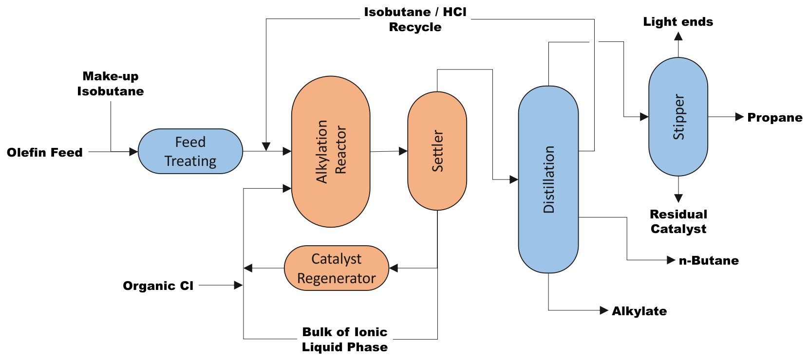
A general process flow diagram for the production of motor fuel alkylate is shown in Fig. 1. Actual designs are tailored to achieve individual refinery needs and objectives.
| Figure 1 - ISOALKY simplified Block Flow Diagram (adapted from Ref. 1-3). |
 |
The reactor design includes injection nozzles for efficient dispersion of the ionic liquid catalyst and an external heat exchanger. There are no moving parts, such as impellers, in the reactor which ensures reliable operation. The reactor can operate in a wide range of olefin feed rates and 50% turn down is feasible.
The process involves the following steps:[1,3]
- Makeup-isobutane and olefin feed are treated to remove water and other contaminants.
- The purified feedstocks are combined with isobutane recycle and sent to the reactor system.
- The reactor system is designed to ensure efficient contacting and mixing of hydrocarbon feed with the ionic liquid catalyst.
- The net effluent from the reactor is phase-separated into the heavier ionic liquid phase and lighter hydrocarbon phase.
- Efficient separation and recovery of the ionic liquid catalyst minimize the loss of the ionic liquid catalyst via carry-over to the distillation section. This separation is achieved with a proprietary liquid-liquid coalescing technology that allows full separation of the ionic liquid catalyst from hydrocarbons.
- The separated, water-clear hydrocarbon stream is sent to the fractionation section.
- The ionic liquid is returned to the reactor.
- Conjunct polymer is formed by undesirable side reactions of olefin and alkylation catalyst. Since it deactivates the catalyst, removal of conjunct polymer is required in order to maintain catalyst activity. A portion of used ionic liquid catalyst is sent to the regeneration unit where the ionic liquid undergoes mild hydroprocessingto remove an amount of the conjunct polymer equal to the amount formed during the alkylation reaction. The unique on-line regeneration converts conjunct polymer into saturated hydrocarbons with gasoline boiling range called “regen naphtha” and lighter hydrocarbons classified as LPG.
- The regeneration unit effluent is sent to the alkylation reactor section where the regen naphtha and LPG are transferred to the hydrocarbon stream and then sent to the distillation section.
- The fractionation section is nearly identical to existing alkylation process designs consisting of a main fractionator, stripper, and product treatment.
- The reactor effluent is fractionated into product streams in the distillation unit.
- Propane is sent overhead and is passed through a stripper for removal of light ends and residual catalyst material.
- Recycle isobutane is produced as a side-draw from the fractionator and sent to the reactor section.
- N-butane product is removed as a lower side draw.
- High quality alkylate is produced from the bottom of the fractionator.
- Typically the propane, butane, and alkylate products will be passed over an adsorbent to remove residual catalyst material before being sent to storage or gasoline blending.
Impact of the ISOALKY catalyst
The ISOALKY process uses a small, in-situ catalyst regeneration scheme, eliminating the need for expensive, sulfur emitting stand-alone or toll-based acid regeneration plants. Unlike conventional alkylation processes that produce a heavy oil byproduct that must be incinerated or blended away, the ISOALKY process produces no heavy oil byproduct. Instead the ISOALKY process converts heavy oil byproduct into valuable product improving overall alkylate yield without the risk of environmental emissions.[1]
Feed Flexibility
The same ISOALKY reactor can accept feedstocks ranging from ethylene to amylene, giving a refinery the option to utilize whichever feedstock is most profitable at a given time.[3]
The ISOALKY technology can process high quality alkylate over a wide range of C3 to C5 olefins, unlike sulfuric alkylation. In fact, sulfuric alkylation requires the C3, C4 and C5 olefins to be segregated in different reaction trains, resulting in sulfuric consumption up to two times greater than with C4-only alkylation. With the ISOALKY process, the olefins do not need to be segregated and the catalyst consumption will be up to 800 times lower than sulfuric when alkylating C3 and C5 olefins. The performance and alkylate quality of 100% isobutylene feed is similar to those of mixed C4 olefins. [1,3]
Undesirable propane and isopentane production and reduction of make-up isobutane requirements also are possible because the ISOALKY process has negligible hydrogen transfer reactions. In other alkylation processes up to 50 % of C3 and C5 olefins can undergo the hydrogen transfer reaction. This is demonstrated by ISOALKY’s negligible production of propane and isopentane and up to 50 percent lower consumption of isobutane when processing C3 and C5 olefins. [1]
Since production of propane, n-butane or n-pentane from the olefin feed during the alkylation step are nearly zero, the formation of isopentane from a mixed C5= feed during the alkylation step is low and the C9 selectivity is high, suggesting that the ISOALKY Technology is ideal for upgrading of C5= to predominantly C9 alkylate gasoline or jet fuel.[3]
Ethylene alkylation is of interest to some refiners, and ISOALKY Technology can make an excellent alkylate product from ethylene. With methane and light gas (H2, N2) removed, a 50%-50% mix of ethane/ ethylene from an FCC unit can be alkylated to make 2,3-dimethyl butane selectively.[3]
ISOLAKY process conditions
Typical process conditions are shown in Table 1 below:[1,2,3]
| Table 1 - ISOALKY Process Conditions |
| Feed moisture requirements |
<1 ppm |
| External feed: Isoparaffin/Olefin ratio |
10 mol/mol |
| Reaction medium |
Hydrocarbon continuous phase with
droplets of ionic liquid catalyst |
| Temperature |
30-120 ⁰F (-1 - 49⁰C) operable window |
| Pressure |
60-250 psig (5.2 - 18.6 kg/cm2) operable window |
| Isobutane/ Olefin molar ratio |
6 -10 external I/O |
| Ionic liquid catalyst volume |
3 - 6 vol% in reactor |
| Olefins conversion |
> 99.9% |
| Alkylate research Octane |
95-99 RON (99 RON achievable at 30°F (-1°C) reactor temperature with typical mixed C4= FCC feed. |
| Conjunct polymer formation |
~0.3% to 0.5 wt% of olefins |
Effect of temperature on Alkylate properties
ISOALKY Technology could produce higher octane number alkylates than other alkylation technologies by operating at ~50°F (10⁰C) reactor temperature or lower. The impact of temperature on alkylate quality is shown in Fig. 2.[3]
| Figure 2 - Alkylate RON and End Point vs. ISOALKY operating temperature. |
 |
Revamp of existing units
Revamps of existing HF and H2SO4 alkylation units that require major modifications to achieve refinery revamp goals should consider incorporating the ISOALKY process flow configuration to increase feed rate and feed flexibility capabilities. Typically, the ISOALKY process solution should be considered when a full reactor/settler replacement
is required to achieve a capacity expansion or when changing the acid catalyst is desired to reduce the risk profile. Existing feed pretreatment and fractionation sections can be repurposed in the ISOALKY process.[1]
Refiners considering retrofit of an existing alkylation unit will be able to utilize the existing downstream equipment without corrosion concerns because the efficient separation of the ionic liquid catalyst enables very high purity of the effluent hydrocarbon stream.[3]
In Fig. 1, the blue boxes are reusable components in case of a revamp, whereas the orange blocks are required new devices.
Comparative advantages with conventional technologies
Table 2 shows the ISOALKY process advantages compared with conventional processes making use of strong acids such as HF or H2SO4):[1,2,3]
| Table 2 - ISOALKY Process key features and comparative advanges |
| Key characteristic |
Used non-volatile ionic liquid catalyst |
| Alkylate yield advantage |
~1+ vol% |
| Alkylate RON |
Generally 2 numbers higher than can be achieved
with H2SO4 process at same temperature |
| Alkylate yield |
Est. 3 vol% advantage compared (vs. H2SO4) |
| Process performance |
Moderate advantage |
| Capital / Operating costs |
Comparable |
| Handling requirements |
Advantaged |
| Key characteristics |
• non-volatile ionic catalyst lliquid
• moderate process performance advantage |
| HSE impact |
• smaller catalyst inventory
• elimination of polymer incineration
• reduces caustic solution waste |
Commercialisation
Chevron U.S.A. Inc. is the technology owner, and UOP is the exclusive licensor of the ISOALKY process.[2]
References
- Version dated 9th Nov 2021, ISOALKY™ Alkylation Process Solution Datasheet, Honeywell UOP.
- Hye-Kyung Timken, 2nd Aug 2017, ISOALKY™ TECHNOLOGY: NEXT GENERATION ALKYLATE GASOLINE MANUFACTURING PROCESS TECHNOLOGY, Chevron.
- Hye Kyung Timken et al., 6th Mar 2020, A New Era for Alkylation: Ionic Liquid Alkylation – ISOALKY™ Process Technology� white paper, Honeywell UOP.


