Basis and Scope
This profile describes a generic, open-art single-column cryogenic turboexpander NGL recovery unit with split-feed subcooling, processing pretreated wet natural gas at a reference scale of 100 MMscfd (2.83 MMSm³/d).
The configuration is based on the Gas Subcooled Process (GSP) principle, whose foundational patent — originally filed by Ortloff Corporation in 1976–1977 — expired by the mid-1990s and whose process scheme is now fully in the public domain. The GSP split-feed configuration is described extensively and independently in open literature, and does not reproduce any currently active licensed process.
Higher C₂ recovery exceeding 95%, achievable through supplemental rectification or overhead vapour recycle configurations, is outside the scope of this profile and is the subject of proprietary licensed processes offered by technology developers as described in the overarching technology description.
Feed Gas Specification (Pretreated Wet Gas):
Wet natural gas arrives from the wellhead or upstream gathering system carrying its full C₂+ content. Before entering this unit, it must have been pretreated in dedicated upstream units (molecular sieve dehydration and mercury removal) but retains all heavier hydrocarbons:
| Component |
Typical Wet Gas Feed (mol%) |
| Methane (C₁) |
70–82% |
| Ethane (C₂) |
7–12% |
| Propane (C₃) |
3–6% |
| Butanes (C₄) |
1–3% |
| Pentanes+ (C₅+) |
0.5–2% |
| Nitrogen (N₂) |
<1% |
| Carbon Dioxide (CO₂) |
<0.5 mol% (freeze-out constraint) |
| Water content |
<1 ppmv (mol sieve dehydrated upstream) |
| Mercury |
<0.01 µg/Sm³ (MRU treated upstream) |
- Inlet pressure: 60–90 bar(g)
- Inlet temperature: 15–40°C
- Feed richness note: When C₃+ exceeds ~10 wt% of feed, supplemental propane refrigeration is required to maintain recovery targets (see Section 3)
Battery Limits:
- In: Pretreated wet gas at battery limit (post-dehydration, post-MRU), C₂+ content intact
- Out (gas): Residue gas (pipeline-quality methane-rich gas) at pipeline pressure
- Out (liquid): C₂+ NGL stream to downstream fractionation train (deethanizer, depropanizer, debutanizer — separate technology profiles)
Section 1 — Step-by-Step Process Description
The process exploits isentropic expansion across a turboexpander to achieve cryogenic temperatures (−90°C to −100°C), condensing C₂+ hydrocarbons from the wet gas stream while methane remains gaseous. No chemical reactions occur; separation is entirely physical and thermodynamic.
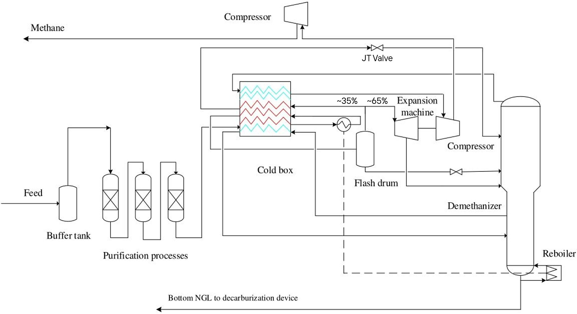
Gas Subcooled Process (GSP) flow diagram, adapted [8]
Step 1 — Feed Gas Entry and Cold Box Pre-Cooling (Stage 1)
Pretreated wet gas enters the unit at 60–90 bar(g) and 15–40°C. It flows into the brazed aluminium heat exchanger (BAHX), Cold Box Stage 1, where it is pre-cooled against cold returning residue gas and demethanizer overhead vapour to approximately −35°C to −50°C. The high-pressure feed remains predominantly vapour at this stage for typical lean-to-medium wet gas feeds.
Step 2 — High-Pressure Separator (HPS)
The pre-cooled feed enters the high-pressure separator (HPS), a two-phase separator vessel operating at feed pressure and approximately −35°C to −50°C. Any C₃+ condensate knocked out here is collected and routed as a separate liquid feed directly to a mid-column feed point on the demethanizer. The vapour fraction continues forward.
Step 3 — Feed Splitting and Subcooling (Cold Box Stage 2)
The HPS overhead vapour is split into two streams:
- Stream A (~30–40% of total vapour flow):
- Routed to Cold Box Stage 2, where it is further cooled against demethanizer overhead to approximately −70°C to −80°C and partially condensed.
- This subcooled liquid is then throttled across a Joule-Thomson (JT) valve, dropping pressure from ~65 bar to demethanizer top pressure (~28–30 bar) with a further temperature drop to approximately −95°C.
- It is injected as cold reflux at the top tray of the demethanizer — the critical feature that drives high C₂ recovery
- Stream B (~60–70% of total vapour flow): Routed directly to the turboexpander inlet
Step 4 — Turboexpander / Booster Compressor
- Stream B (warm wet vapour) expands isentropically through the turboexpander (radial inflow type), dropping from ~65 bar to ~28–30 bar. The isentropic expansion causes a temperature drop to approximately −90°C to −100°C, condensing the C₂+ fraction as the stream partially liquefies.
- The shaft work recovered from expansion directly drives the integrally coupled booster compressor, which partially recompresses the cold residue gas leaving the demethanizer overhead.
- The two-phase expander outlet stream feeds the demethanizer at a mid-to-lower column feed point.
Step 5 — Demethanizer Column
The demethanizer is the heart of the separation. It receives three feed streams:
- (a) cold subcooled reflux at the top (Step 3)
- (b) two-phase turboexpander outlet at mid-column (Step 4)
- (c) HPS liquid condensate at a lower mid-column point (Step 2)
Operating conditions:
- Top pressure: ~28–30 bar(g)
- Top temperature: ~−95°C (controlled by reflux flow)
- Bottom temperature: −10°C to +20°C (reboiler duty dependent on feed richness)
- Column internals: ~20–28 trays or structured packing
The overhead vapour is a methane-rich residue gas (>97 mol% C₁); the bottoms is the C₂+ NGL product stream. The reboiler provides heat to strip dissolved methane from the NGL bottoms and ensure on-spec residue gas overhead.
Step 6 — Residue Gas Recompression
The cold demethanizer overhead vapour is warmed through the Cold Box (Stages 2 and 1), recovering refrigeration against incoming feed and subcooled reflux streams. It exits the cold box near ambient temperature and is then compressed in two stages:
- Stage 1: Booster compressor (turboexpander-driven) raises pressure from ~28–30 bar to ~40–45 bar, recovering ~70–80% of the expansion energy
- Stage 2: Residue gas compressor (motor or gas turbine driven) raises pressure to pipeline specification (~65–80 bar)
The residue gas is air-cooled to ~40–50°C before export.
Step 7 — NGL Product Rundown
The demethanizer bottoms (C₂+ NGL) are pumped via the NGL product pump to the downstream NGL fractionation train at the battery limit. Typical NGL product temperature at battery limit: −10°C to +10°C.
Optional Step 8 — Supplemental Propane Refrigeration (Rich Gas)
When wet gas feed richness exceeds ~10 wt% C₃+, an external propane mechanical refrigeration system is added to pre-cool the feed ahead of the Cold Box, restoring propane recovery to >99%. Refrigeration duty ranges from ~17 to 308 refrigeration tons (60 kW – 1,085 kW) depending on feed richness.
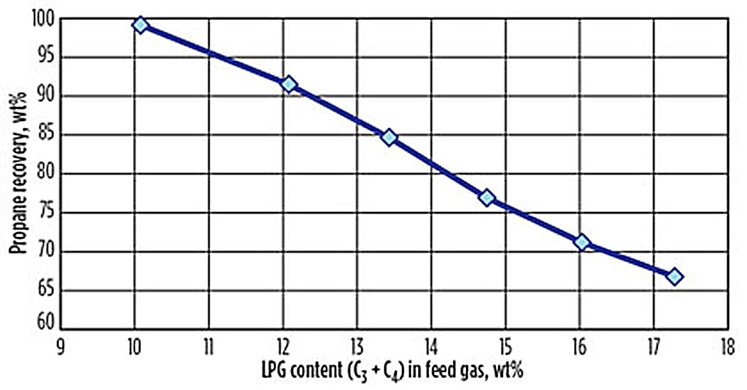
Propane recovery vs. LPG in feed gas [15]
Section 2 — Equipment List
| Tag* |
Equipment Item |
Key Parameters |
| E-101A/B |
BAHX Cold Box
(Stage 1 + Stage 2) |
Brazed aluminium, multi-stream; ΔT min approach ~3–5°C; operates to −100°C |
| V-101 |
High-Pressure Separator |
2-phase separator vessel;
T = −35 to −50°C; P = 60–65 bar |
| JT-101 |
Joule-Thomson Valve (subcooled reflux stream) |
Pressure letdown ~65 bar → ~28 bar; T outlet ~−95°C |
| K-101 |
Turboexpander
(radial inflow) |
Inlet ~65 bar / −70°C; outlet ~28 bar / −95 to −100°C; isentropic efficiency ~85–88% |
| K-102 |
Booster Compressor (expander-coupled) |
Integrally coupled to K-101; raises ~28–30 bar → ~42 bar |
| T-101 |
Demethanizer Column |
20–28 trays or structured packing; P ~28–30 bar; T top ~−95°C; T btm ~−10 to +20°C |
| E-102 |
Demethanizer Reboiler |
Thermosiphon or kettle; duty ~1–3 MMBtu/hr per 100 MMscfd |
| K-103 |
Residue Gas Compressor |
Motor or gas turbine driven; ~42 bar → ~70–80 bar pipeline spec |
| E-103 |
Residue Gas Aftercooler |
Air-cooled; outlet T ~40–50°C |
| P-101 |
NGL Product Pump |
Demethanizer bottoms to fractionation battery limit |
| E-104 |
Propane Refrigeration Package (optional) |
Required when feed C₃+ >10 wt%; duty 0.2–3.7 MMBtu/hr |
| V-102 |
Fuel Gas KO Drum |
Liquids separation from plant fuel gas supply |
*Legend: E- = Heat exchanger • V- = Vessel / separator • K- = Compressor, expander (rotating machinery) • T- = Tower / column • P- = Pump • JT- = Joule-Thomson valve
Section 3 — Separation Efficiency and Yields
| Component |
Recovery into NGL (typical) |
Notes |
| Ethane (C₂) |
75–85% |
Standard GSP split-feed configuration* |
| Propane (C₃) |
>99% |
Near-complete in all turboexpander configurations |
| Butanes (C₄) |
>99% |
Essentially complete |
| Pentanes+ (C₅+) |
~100% |
Complete |
| Methane in NGL bottoms |
<0.5 mol% |
Controlled by demethanizer reboiler duty and reflux rate |
*Legend: higher C₂ recovery exceeding 95% is achievable through supplemental rectification or overhead vapour recycle configurations, which are the subject of proprietary licensed processes
Recovery sensitivity factors:
- C₃ recovery degrades from ~99% to ~67% when feed C₃+ exceeds ~10 wt%, unless supplemental refrigeration is applied
| Propane recovery vs. LPG in feed gas [15] |
.
- Optimal demethanizer pressure is ~28–29 bar; lower pressures improve C₂ recovery but increase recompression power demand
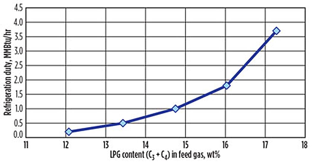 Refrigeration duty vs. LPG in feed gas [15] Refrigeration duty vs. LPG in feed gas [15] |
..
- Turboexpander isentropic efficiency of 85–88% is the primary driver of cold box outlet temperature and overall C₂ yield
- CO₂ content must remain below 0.5 mol% to avoid dry ice formation in the cold section
Indicative NGL yield (100 MMscfd wet gas basis, medium-richness feed):
- NGL product: ~1,500–3,500 bbl/day (strongly feed-composition dependent)
- Residue gas: ~85–92 MMscfd (C₁-rich, pipeline spec)
Section 4 — Process Economics
CAPEX (Indicative, 100 MMscfd Basis, 2024 USD)
| Cost Element |
USD (MM) |
| Turboexpander + Booster Compressor package |
4–7 |
| Cold Box (BAHX, multi-stream) |
5–10 |
| Demethanizer column + internals + vessel |
3–6 |
| Residue gas compressor (motor-driven) |
5–12 |
| Heat exchangers, vessels, separators, piping |
4–8 |
| Instrumentation and control |
3–5 |
| Electrical, civil, structural |
4–7 |
| EPC indirects + contingency (~25–30%) |
8–14 |
| Total Erected CAPEX |
~36–69 MM |
The wide range reflects inlet pressure (higher pressure reduces compressor cost), recovery target mode (ethane recovery vs. propane-only), feed richness, and plant location. Modular pre-engineered packages (e.g. UOP Russell SR-series) are available for smaller scales and compress both schedule and cost.
OPEX (Annual, 100 MMscfd Basis, 2024 USD)
| Cost Element |
USD/yr (MM) |
| Residue gas recompression power (dominant) |
2.0–4.5 |
| Maintenance (~2–3% of CAPEX/yr) |
0.7–2.0 |
| Operator labour |
0.3–0.8 |
| Cooling / air cooler utilities |
0.1–0.3 |
| Propane refrigerant make-up (if applicable) |
0.1–0.3 |
| Total OPEX |
~3.2–7.9 MM/yr |
Recompression power dominates OPEX. The turboexpander recovers ~70–80% of compression work, making it substantially more energy-efficient than a pure JT expansion alternative.
Revenue and Payback Context
- At propane ~$400–600/t and ethane ~$150–250/t, a 100 MMscfd plant on medium-rich wet gas generates approximately $35–85 MM/yr gross NGL revenue
- Payback periods of 1–3 years are typical for greenfield NGL recovery additions to existing wet gas gathering systems
PFD Boundary Definition
| Boundary |
Scope |
| In scope |
Cold Box (BAHX), HPS, JT valve, turboexpander/booster compressor, demethanizer + reboiler, residue compressor + aftercooler, NGL pump, optional propane refrigeration package |
| Feed battery limit |
Pretreated wet gas (dehydrated, mercury-removed),
C₂+ intact, at 60–90 bar(g), 15–40°C |
| Residue gas battery limit |
Pipeline-quality methane-rich gas at pipeline pressure
(~65–80 bar), ~40–50°C |
| NGL battery limit |
C₂+ NGL liquid to fractionation train |
| Excluded (separate profiles) |
Molecular sieve dehydration; Mercury Removal Unit (MRU);
NGL fractionation (deethanizer, depropanizer, debutanizer) |
References
- Honeywell UOP — UOP Ortloff™ Natural Gas Liquids Recovery: Optimal Recovery for Maximized Returns, Product Brochure UOP8424, April 2019. UOP LLC, Des Plaines, IL, USA
- Honeywell UOP — UOP Russell NGL Recovery: Cryogenic Turboexpander Plant, Product Datasheet UOP4524-22b, July 2016
- McDermott Technology — Yamin F. et al., Advances in NGL Recovery Technology: Achieving Ultra-High Ethane Recovery and Deep Ethane Rejection Capability, GPA-GCC 27th Annual Technical Conference, Kuwait, March 12–14, 2019
- Technip Energies — Gas Monetization: CRYOMAX® NGL Recovery Technology, corporate technology overview (Accessed Mar 24, 2026)
- Wood Group Mustang — Smith L., Processing Rich Gas for NGL Recovery, GPA Canada Conference Presentation (Document date: October 28, 2015)
- Oil & Gas Journal — Simulation Study Determines Optimum Turboexpander Process, Oil & Gas Journal, March 5, 2006
- Oil & Gas Journal — Enhanced NGL Recovery Process Selected for Neptune Gas Plant Expansion, Oil & Gas Journal, July 20, 2003
- Li Y., Xu F., & Gong C. (Aug 2017). System optimization of turbo-expander process for natural gas liquid recovery. Chemical Engineering Research and Design, 124, 159-169. DOI: 10.1016/j.cherd.2017.06.001
- United States Patent — US5799507A, Hydrocarbon Gas Processing, filed October 25, 1996 (Elk Corp)
- United States Patent — US20140060114A1, Configurations and Methods for Offshore NGL Recovery, filed August 29, 2013 (Fluor Technologies Corp)
- Petrotech — Turboexpanders in NGL Recovery, March 28, 2025
- LinkedIn — Rodon J.R., Maximizing NGL Recovery: Understanding the Turbo-Expander Cryogenic Process, January 29, 2025
- LinkedIn — Barthe L., NGL Recovery: Evolution and Next Generation Processes, Jan 22, 2016
- Butane-Propane News — Lummus Technology Selected for Innovative Gas Processing Plant with High Efficiency & Low Carbon Design, January 28, 2022
- Energy Enterprise Associates — Hani M., Use Refrigeration to Boost Liquids Recovery from LPG-Rich Gas, Gas Processing News, February 2, 2015
- Specialized Consulting Services — Habibullah A., Turboexpander Plants: Large Single Train Design (Document date: October 14, 2017). Academia