Waste-to-Energy Plants
Incinerators are also called Waste-to-Energy (WtE) plants, or Energy-from-Waste plants (EfW).
Incineration Technologies
Incineration is the oldest technology used to process waste, consisting of several types of incinerators such as:
- Grate Incinerators
- Fluidized Bed Technologies
- Rotary Kiln Incinerators
They all involve directly combusting the MSW in an Oxygen-rich environment, typically at temperatures between 700°C and 1,350°C. An exhaust gas composed primarily of CO2 and water is produced, which flows through a boiler to produce steam to drive a steam turbine generator, producing electricity. Inorganic materials in the MSW are converted to bottom ash and fly ash. These by-products must be disposed in controlled and well-operated landfills to prevent ground and surface water pollution. Although incineration does not eliminate the need for landfills, it does significantly reduce the amount being sent to landfills by about 90% by volume.[1]
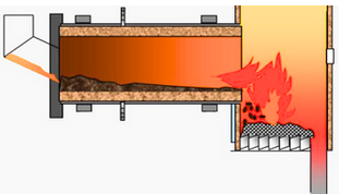
Stoker Type Incineration Plants / Thermal Treatment on Grate
Mass burn is the incineration on a grate of bulk waste that has not undergone sorting, classification or size reduction of any type. The main advantage is that garbage is fed as it comes (except that very large pieces more than around 1m and bulky items have to be shredded) and it is said to be the most efficient solution for handling household waste. Sometimes it is combined with some upfront selective collection according to requirements of the local municipalities. With population size increase and the development of large urban centres the trend is going towards larger mass burn capacity plants. Mass burn is obviously not suitable for smaller volumes where instead alternative technologies could be employed.[2]
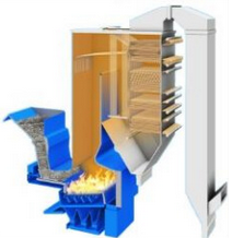
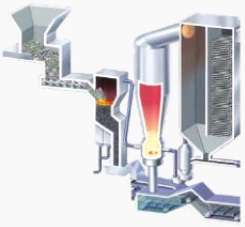
Figure 1 - Grate Incinerator Schematics[3]
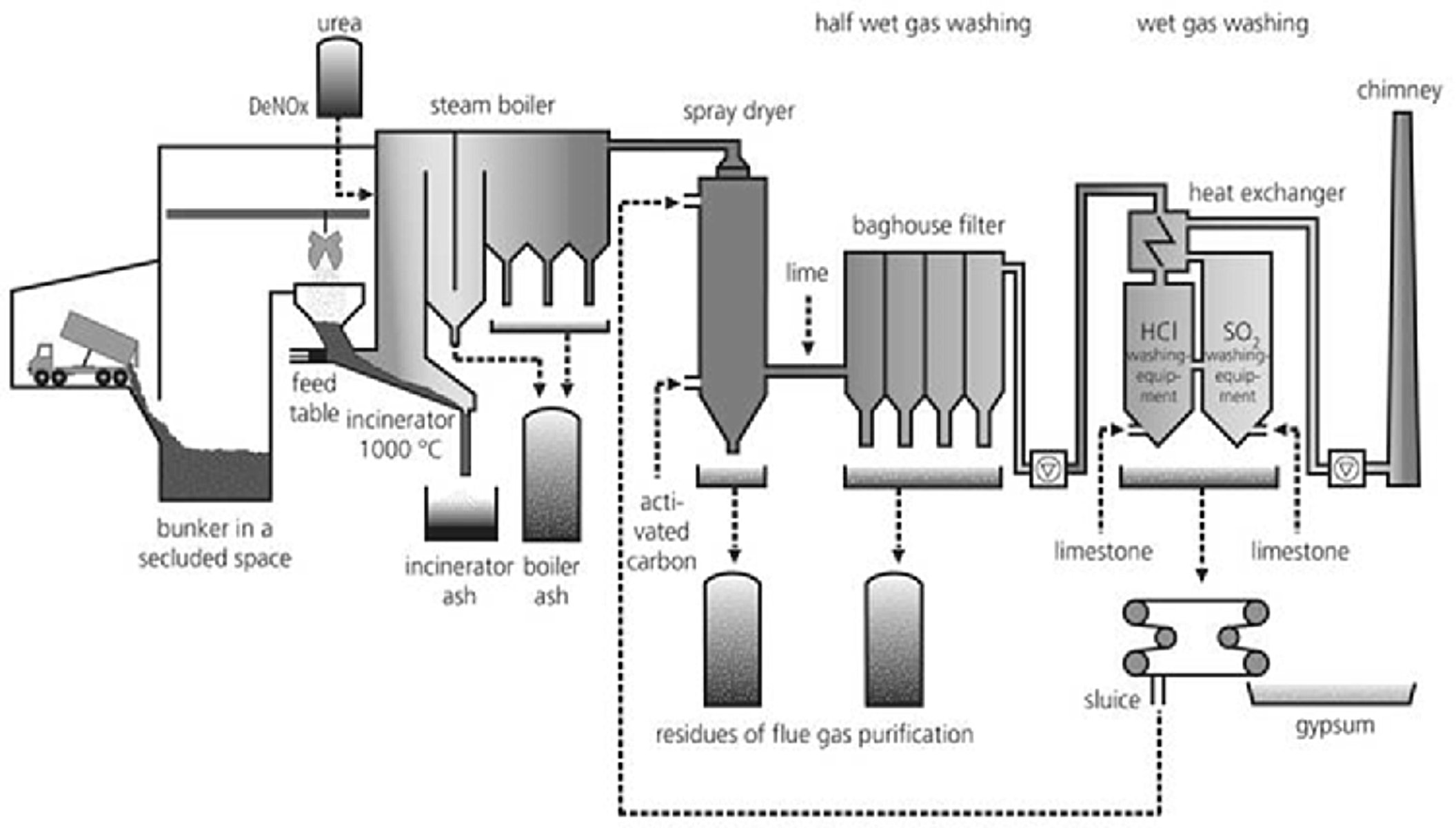
The waste is first dried on the grate and then burnt at a high temperature (850 to 950°C) accompanied with a supply of air. With a crane, the waste itself is emptied into an opening in the grate. The waste then moves towards the ash pit and it is then treated with water, cleaning the ash out. Air then flows through the waste, cooling the grate. Sometimes grates can also be cooled with water instead. Air gets blown through the boiler once more (but faster this time) to complete the burning of the flue gases to improve the mixing and excess of oxygen.[4]
Comparison of Incineration Technologies
Mitsubishi provides three types of solid WtE technologies with the following compared in Table 1[5].
Table 1 - Comparison of different types of Mitsubishi incinerator technologies[5].
| Incinerator Type |
Stoker |
Gasification &
Ash Melting |
Rotary Kiln Stoker |
| Schematics |
 |
 |
 |
| Capacity per Unit |
100-1,000
tonnes per day |
100-200
tonnes per day |
100-250
tonnes per day |
| Waste Type |
MSW
Industrial Waste Biomass |
MSW |
Industrial waste |
| Advantages |
Construction costs
Waste flexibility
Proven records |
Recycling of
valuable metals
and slag |
Wide range
of waste types
is acceptable |
| Disadvantages |
Ash generation |
Construction costs |
Industrial waste only
(higher Lower Heating Value) |
Incineration Plants Capacities
In 2013, Mass Burn on Grate accounts for 174 million annual tonnes, Fluidized Bed for 12 million annual tonnes, and other technologies (e.g., direct smelting, rotary kiln, etc.) for 2.9 million annual tonnes. Therefore, in terms of waste combustion capacity, Mass Burn accounts for 92.1% of the global capacity, and Fluidized Bed for only 6.4%. It is noteworthy that several of the main incineration technology providers only offer mass burn but no alternative incineration technologie[6].
By 2018, roughly 2,430 WtE plants are active worldwide, which constitute roughly 360 million tons of disposal capacity[7].
The minimum size, from an economic viewpoint, for a Waste-to-Energy plant is around 40,000 t/year. The largest plants have capacities of more than 1 million tonnes per year. Individual combustion lines can have capacities from around 2.5 to 50 tonnes per hour (20,000 to 400,000 tonnes per year, whereby the more typical range is 5 to 30 tonnes per hour (40,000 to 240,000 TPA). A Waste-to-Energy plant is expected to run for at least 8,000 hours per year, roughly 94% of the time[8].
The largest mass burn incinerator is the Laogang Renewable Resource Recycling Center, which first and second phases combined are able to burn 3 million tons of garbage per year. The second phase of the center has eight incinerators that allow it to process about 6,000 tons of garbage daily, corresponding to a 250,000 tonnes capacity per incinerator. The plant can generate up to 1.5 billion kilowatt hours of power[9].
Japan Steel Eng. claims to currently hold the record for largest operating plant per line at 864 tonnes per day, corresponding to about 290,000 tonnes per year, and with a maximum design capacity of 1,200 tonnes per day, which is also the largest in the world[10].
References
- Adapted from: Yuzhong Tan, 15th Apr 2013, College of Engineering, University of California, Berkeley: Feasibility Study on Solid Waste to Energy - Technological Aspects.
- CNIM personal communication.
- Vermeulen, Isabel et al.: Sustainable waste processing in a grate furnace and in a fluidized bed incinerator: WtE, recycling and environmental concerns, WIT Transactions on State-of-the-art in Science and Engineering 84 (2014): 83-92.
- Rachael Lew, 29th Nov 2022, BioEnergyConsult, Moving Grate Incineration: The Most Common WTE Technology.
- MHIEC Company and Waste to Energy Technology.
- Olivier Morin, 7th Oct 2014, Technical and Environmental Comparison of Circulating Fluidized Bed (CFB) and Moving Grate Reactors, Columbia University, Earth Engineering Center.
- Richard Ling, Mar 2019, Powering Our Future with Trash, Kleinman Center for Energy Policy.
- ESWET website, accessed Apr 2020.
- Xu Lingchao Hu Min Zhong Youyang, 29th Jun 2019, Asia's biggest solid waste treatment base goes above and beyond, SHINE.
- NIPPON STEEL & SUMIKIN ENGINEERING Group’s Waste to Energy System.