Extractive distillation (ED) is used to separate azeotropic or close-boiling mixtures that are difficult to resolve by ordinary distillation. A selectively interacting solvent (entrainer) is introduced separately from the feed to modify the mixture’s vapour–liquid equilibrium and relative volatility. In a common continuous arrangement, the more volatile component is taken overhead from the extractive column, while the solvent-rich stream is sent to a recovery column; recovered solvent is recycled, with make-up as needed. Solvent properties, product split and column configuration are mixture-specific, so a flowsheet or simulation for one pair of components should be treated as an example rather than a general design rule.[1][2][3]
Illustrative iso-octane–toluene separation with phenol
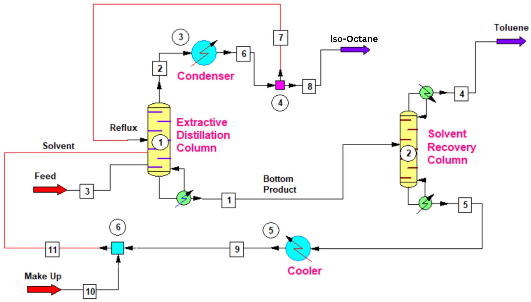
The accompanying schematic illustrates a two-column arrangement for separating a feed into iso-octane and toluene using phenol. The flowsheet depicts this two-column arrangement with extractive-column overhead condensation and reflux, an extractive-column bottoms stream to solvent recovery, a solvent recycle through a cooler, and a make-up addition.[4]
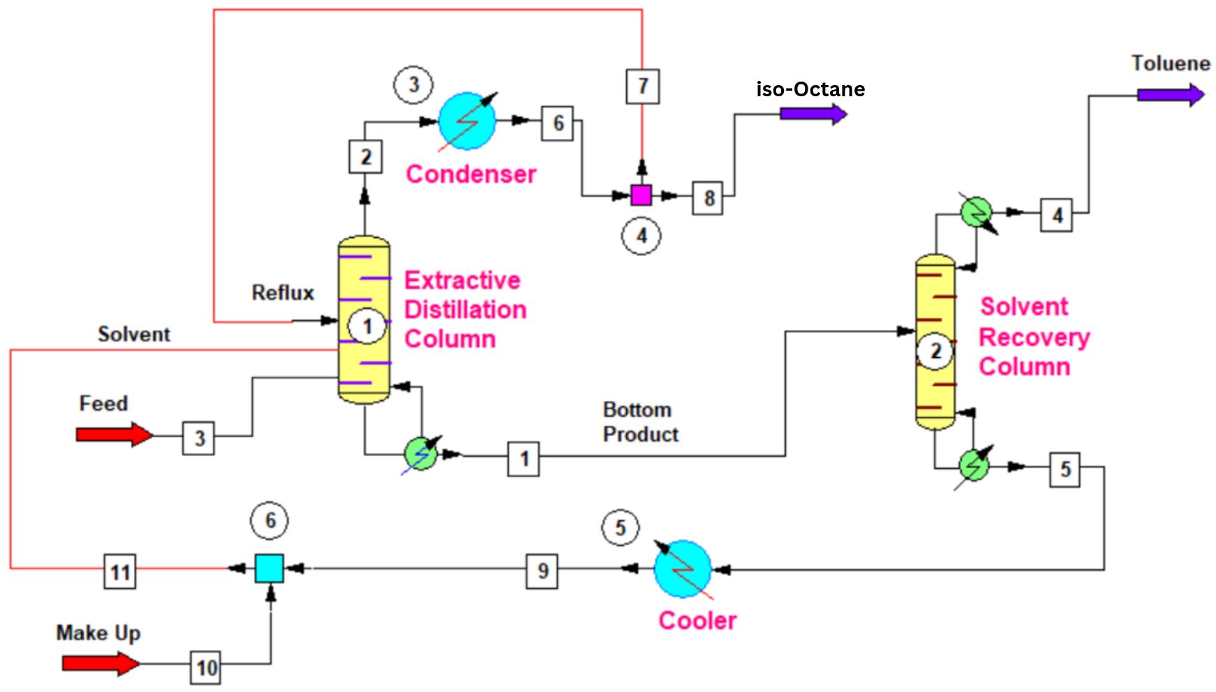
- Extractive column: [3] The feed enters the lower-to-middle part of the first column (1), while [11] solvent enters separately below the reflux entry. The solvent preferentially changes the volatility relationship of the feed components. [2] Overhead vapour is condensed (3); [7] part of the condensate returns to the column as reflux, while [8] the remaining stream leaves as the n-octane product.
- Solvent recovery: [1] The liquid leaving the extractive column bottoms—shown as the “Bottom Product” stream in the schematic—is routed to the second column (2). There, [4] toluene leaves overhead as the second product, while [5] solvent is recovered in the bottoms.
- Solvent recycle: The recovered solvent bottoms are cooled (5) and [9] returned to the extractive column. [10] A make-up stream joins the recycle (6) before [11] it returns, representing replacement of solvent losses. The diagram also shows a condenser (3)and reflux return (4) on the extractive column and a cooler (5) on the solvent-recycle line.
Thus, in this depicted arrangement, the first column produces an n-octane-rich distillate and sends a toluene/solvent-rich bottoms stream to solvent recovery; the recovery column separates toluene overhead from the solvent recycle. “Bottom Product” labels the inter-column stream in the drawing, not a final product leaving the overall process.
Reported CHEMCAD simulation
The article reports a CHEMCAD simulation at atmospheric pressure with a feed rate of 1,000 kg/h, comprising 60 wt.% iso-octane and 40 wt.% toluene. It gives normal boiling points of 99 °C for iso-octane and 110.6 °C for toluene, and reports that conventional distillation becomes difficult above about 85 wt.% iso-octane, with an azeotrope at 98.77 °C. Phenol, reported to boil at 181.7 °C, is used as solvent; the article states that its presence increases the relative volatility of iso-octane.[4]
- Extractive-distillation column: 30 theoretical trays. The phenol flow is 2,881 kg/h and it is introduced at stage 3 from the top; the feed enters at stage 11 from the top. Reflux returns at the top stage; the reported reflux flow is 3,500 kg/h and the reflux ratio is 1:5.8 (rounded in the article to about 1:6). The reported iso-octane distillate purity is 99.17 wt.%.
- Solvent-recovery column: 20 theoretical stages; feed enters at stage 10 and the reported reflux ratio is 1:5. The article’s material-balance discussion identifies stream 4, the recovery-column distillate, as toluene at 99.99 wt.%.
- Thermodynamic method: UNIFAC.
Solvent selection and process design
A suitable solvent must provide useful selectivity while remaining practical to recover and recycle. Selection and design consider its effect on relative volatility across the operating composition range, volatility and carry-over into product streams, solvent-to-feed ratio, thermal and chemical stability, materials compatibility, and the energy and cost of regeneration. Improving separation in the extractive column alone is not sufficient: the recovery column and recycle loop can affect both overall energy use and attainable product purity. Thermodynamic feasibility and column configuration should therefore be assessed for the integrated separation and solvent-recovery system. Depending on the mixture and design objectives, alternatives may include different entrainer classes or column arrangements, and options such as heat integration or divided-wall columns.[1][2]
References
- Chemical Engineering Research and Design — Review of extractive distillation: Process design, operation, optimization and control (Jan 2019), Vincent Gerbaud et al., vol. 141, pp. 229–271. DOI: 10.1016/j.cherd.2018.09.020.
- University of Twente Research Information — Solvent selection for extractive distillation processes to separate close-boiling polar systems (Apr 1, 2019), Lisette M.J. Sprakel et al., Chemical Engineering Research and Design, vol. 144, pp. 123–134. DOI: 10.1016/j.cherd.2019.01.024.
- EPIC Process Systems — How Extractive Distillation is like Getting Gum out of your Hair (undated; source of the existing ppPLUS description text).
- K. Mehra. Extractive Distillation Method for Azeotropes (Mar 17, 2021)— ChemEnggHelp