Some text some message..


Line 1

Line 2

Name
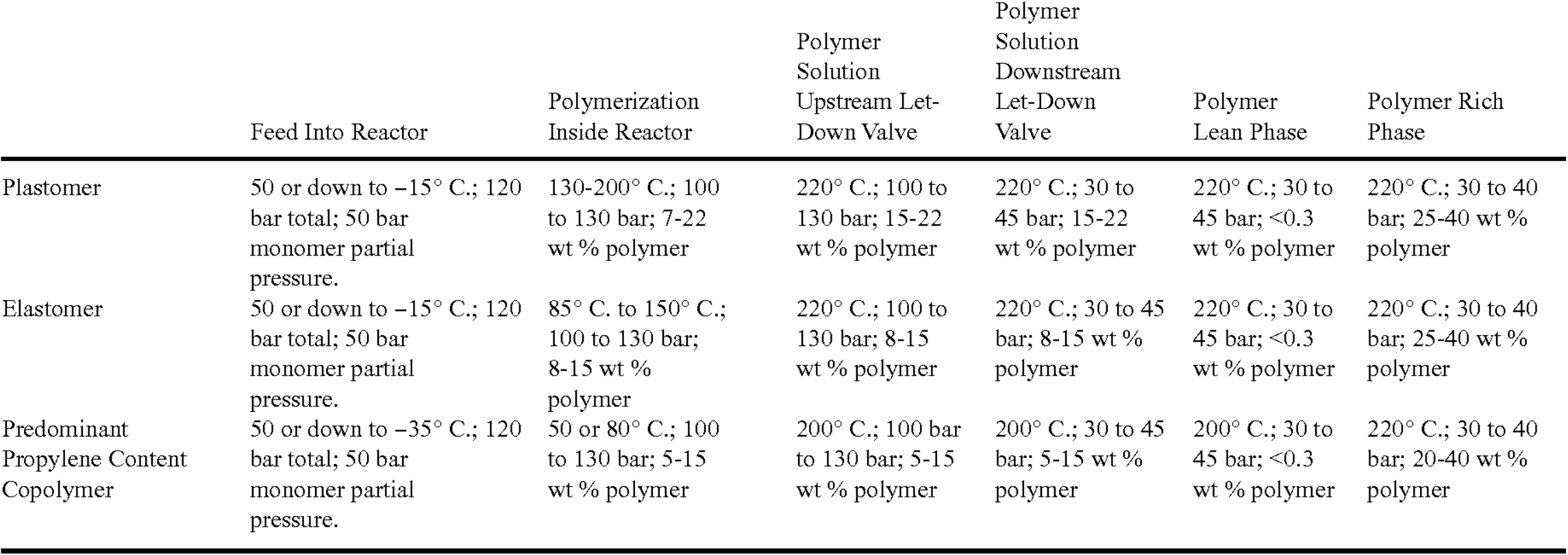
ExxonMobil Solution Process
Owner
/ Exxonmobil Limited
Brand
ExxonMobil Continuous Solution Process
Process
Polyethylene processes
Type
Solution Polymerization of Ethylene
Available

To make Plastomer in the Plant depicted in the Process Flow Diagram:

  • The feed temperature is reduced by the chiller (6) to 0° C. Aluminum alkyl is added as scavenger in amounts appropriate to the poison content of the feed.
  • The pressure is raised by the centrifugal pump to 120 bar.
  • The feed comprising largely solvent and up to 50 bar partial pressure of ethylene and butene or hexene or octene comonomer then enters the first of the two series reactors (8).
  • Catalyst and activator is added to the reactors (8) in amounts to create the desired polymerization temperature which in turn is related to the desired molecular weight. The heat of polymerization increases the temperature to 150° C. to 200° C. to form a plastomer without the use of hydrogen (although H2 may be used).
  • At the outlet of the second series reactor, the polymer concentration is in the range of from 15 wt % to 22 wt %.
  • Water is then supplied at (10) to kill the polymerization reaction which might otherwise continue in the presence of surviving catalyst, unreacted monomer, and elevated temperature.
  • The heat exchanger (12) raises the temperature initially and then the further heat exchanger (16) causes a further temperature rise to 220° C.
  • A rapid pressure drop results as the polymerization mixture passes through the let-down valve (18) into the liquid phase separator, with the pressure dropping quickly from 100 bar to 40 bar.
  • The pressure differential between that at the outlet of the pump (3) and the outlet of the let down valve (18) is solely responsible for causing the feed and the polymerization mixture to flow through the reactor (8) and the conduit (11) including the heat exchangers (12) and (16).
  • Inside the liquid phase separator (14) an upper lean phase is formed with less than 0.1 wt % of polymer and a lower polymer rich phase with 30 wt % to 40 wt % of polymer. The concentration is approximately double to triple that of the polymerization mixture fed to the separator (14).
  • After further removal of solvent and monomer in the low-pressure flash tank (34) the concentrated polymer phase is pumped through gear pump (38) and molten stabilizer, octadeyl-3-(3,5-di-tertbutyl-4-hydroxyphenyl)-proportionate (Irganox 1076, m.p. 50-55° C.) is added at point (38) a at a rate designed to give a concentration of stabilizer in the polymer of approximately 500 ppm.
  • Immediately downstream of stabilizer addition point (38), the concentrated polymer phase enters the devolatilizer (40).
  • Polymer leaving the devolatilizer (40) may contain less than 1 wt %, preferably with 0.3 wt % or less, even more preferably <0.1 wt % of volatiles, including water.
  • Two reactors in series may be used. Generally speaking, in a series layout it is more preferable that the first reactor operates at temperatures between 20° C to 70° C and the second reactor operates between 60° C to 110° C. With appropriate control of process conditions and poison levels temperature of this order of magnitude may also be obtained where one reactor only is used or two reactors are used under the same process conditions.
  • The same may be said about the row in Table 1 marked “Predominant propylene content copolymer” where the temperature is lowered to allow the less reactive propylene monomer to form a sufficiently high molecular weight. The polymerization temperature varied between 28° C and 70° C.

Table 1 - Process Conditions of the Plant/Process in Varying Operating Modes

Source: ExxonMobil, US20110172337A1, Priority Date 17 Dec 2010, Processes and Apparatus for Continuous Solution Polymerization

Link
System Info

Updated by
UserPic  Kokel, Nicolas
Updated
5/27/2023 5:31 PM
Added by
UserPic  Kokel, Nicolas
Added
5/27/2023 5:00 PM
Solutions
Solutions

Solution-Reference:

#TT229

No Services yet available.
Enquire in Solutions how we can help you.

US20110172337A1 - Continuous Solution Polymerization Process Flow Diagram
Entity Site (Country) Asset (Plant)