Process Steps, Conditions & Parameters
Step 1 — Alumina Feed Preparation
SGA (smelter-grade alumina) from the Bayer process is received, stored and fed continuously or semi-continuously to the electrolytic cells via point feeders (automated alumina dispensers). Alumina must meet strict specifications for particle size, surface area, α-Al2O3 content and moisture to ensure good dissolution and avoid crust formation.
| Parameter |
Value |
| Al2O3 purity |
≥98.5% |
| Moisture content |
<0.5% |
| α-Al2O3 content |
5–25% (balance γ-Al2O3) |
| Feed rate control |
Automated point feeders, demand-controlled |
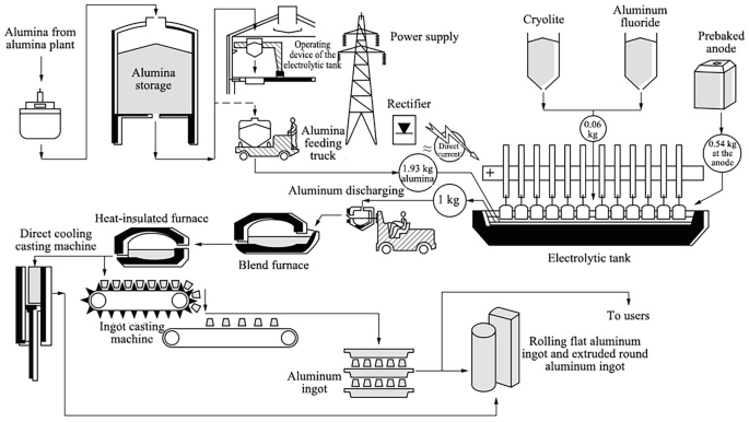
Figure 1 — Schematic process flow of the Hall-Héroult Process (source)

Step 2 — Electrolytic Reduction (The Pot)
The core of the process is the electrolytic cell (pot) — a rectangular steel shell lined with carbon/graphite cathode blocks and refractory insulation. The molten bath fills the cell and is covered by a solidified crust of bath material and alumina. The carbon anodes (either Söderberg continuous self-baking anodes or prebaked carbon anodes) are suspended from an anode beam into the bath from above.
Figure 2 — Hall-Héroult electrolytic cell (source)
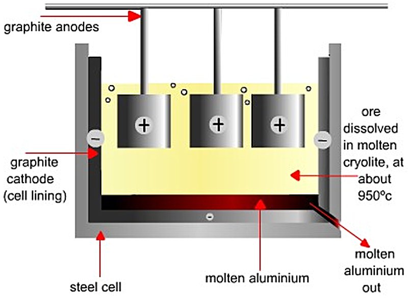
Direct current enters via the anodes, passes through the molten bath, and exits via the cathode lining at the base. Liquid aluminium, being denser than the bath, collects as a liquid metal pad on the cathode floor and is protected by it from re-oxidation.
| Parameter |
Value |
| Bath temperature |
950–980°C |
| Cell voltage |
3.9–4.5 V (thermodynamic minimum ~1.2 V) |
| Line current |
150,000–600,000 A (150–600 kA) per cell |
| Alumina concentration in bath |
2–5 wt% |
| Bath ratio (NaF/AlF3 molar) |
2.2–2.4 |
| Interpolar distance (ACD) |
4–5 cm |
| Current efficiency |
92–96% |
| Specific energy consumption |
13–15 MWh/t Al |
| Carbon anode consumption |
~420–450 kg/t Al |
| Cell (pot) life |
5–10 years before relining |
Step 3 — Metal Tapping
Liquid aluminium (typically ~99.7% purity) is tapped (siphoned or vacuum-lifted) from the pot every 24–48 hours using a crucible-based vacuum tapping system. Metal is transferred in large crucibles to the cast house.
Step 4 — Anode Change
In prebaked anode (PBA) technology, individual carbon anode blocks (~1,000–1,500 kg each) are consumed over approximately 24–28 days and must be replaced regularly. Each pot carries 18–40 anode blocks simultaneously at different stages of consumption. Anode stubs (spent anode butts) are recovered and recycled in the anode baking facility.
In Söderberg technology, continuous anode paste is fed from above and bakes in situ using waste heat from the cell — eliminating the separate anode baking plant but producing more PAH (polycyclic aromatic hydrocarbon) emissions. Söderberg technology is being phased out globally.
Step 5 — Gas Treatment (Dry Scrubbing)
Each pot generates HF gas, CO2, CO, SO2 and PFC gases (CF4 and C2F6 during anode effects). These are captured by a hooding and duct system and treated in a dry scrubbing plant where the gases pass through a bed of fresh alumina, which adsorbs the fluoride gases. The fluoride-laden alumina is then fed back to the pots as part of the regular feed — simultaneously treating the gas stream and recovering fluoride back into the process. Residual gases pass through bag filters before emission.
Step 6 — Casting
Liquid aluminium from tapping crucibles is transferred to the cast house, where it is:
- Held in holding/melting furnaces (gas-fired)
- Alloyed as required by adding silicon, magnesium, copper, manganese, etc.
- Degassed (nitrogen/argon purging or rotary degassing) to remove dissolved hydrogen
- Filtered through ceramic foam filters to remove inclusions
- Cast into standard product forms: T-bar ingots, sow ingots, rolling slabs, extrusion billets or wire rod via DC (direct chill) casting
Key Equipment & Devices
| Equipment |
Function |
Key Specifications |
| Electrolytic Pots (Cells) |
Core electrolysis vessel |
Steel shell, carbon-lined cathode, 150–600 kA current |
| Prebaked Carbon Anodes |
Consumable oxidation electrode |
~1,000–1,500 kg blocks;
replaced every 24–28 days |
| Söderberg Anode System |
Continuous self-baking anode |
Paste fed from top;
being phased out |
| Anode Beam / Busbar |
Current distribution and anode positioning |
Hydraulically adjusted
for ACD control |
| Point Feeders |
Automated alumina dosing into bath |
Demand-controlled;
typically 2–4 per pot |
| Potline DC Rectifiers |
Convert AC grid power to high-amperage DC |
Thyristor rectifier stations;
150–600 kA |
| Busbar Network |
Inter-cell current conductors |
Aluminium/copper busbars; precisely engineered for
magnetic field compensation |
| Vacuum Tapping Crucibles |
Remove liquid metal
from pots |
3–5 t capacity; transported
by overhead crane |
| Pot Tending Machines (PTM) |
Crust breaking, anode change, metal tapping |
Rail-mounted; semi-
or fully automated |
| Gas Collection Hooding |
Capture pot gases
(HF, CO2, PFC) |
Sealed pot covers
with suction ducting |
| Dry Scrubbers (Alumina Adsorbers) |
Remove fluoride
from pot gases |
Countercurrent fluoride adsorption on alumina |
| Bag Filters |
Final particulate removal from exhaust gas |
High-efficiency
fabric filters |
| Anode Baking Furnace |
Bake green carbon anodes to prebaked state |
Ring furnaces;
~1,100–1,150°C |
| Rodding Shop |
Attach cast iron stubs
to baked anodes |
Thimble casting;
mechanical assembly |
| Holding/Melting Furnaces |
Hold and alloy liquid metal in cast house |
Gas-fired tilting furnaces;
30–80 t |
| DC Casting Equipment |
Solidify metal into billets/slabs/ingots |
Direct-chill (DC)
casting tables |
| Degassing Units |
Remove H2 from
liquid metal |
Rotary impeller degassing (SNIF, Hycast) |
References
- Mandin P., Wüthrich R., & Roustan H. (2009). Industrial Aluminium Production: the Hall–Héroult Process Modelling. ECS Transactions, 19(26), 1–10. DOI: 10.1149/1.3247986
- Coursol P., Dufour G., Coté J., Chartrand P., & Mackey P. (Sep 25, 2012). Application of Thermodynamic Models for Better Understanding and Optimizing the Hall–Héroult Process. JOM, 64(11), 1326–1333. DOI: 10.1007/s11837-012-0426-x
- Sadighi S., Mohaddecy R.S., & Ameri Y.A. (2015). Artificial Neural Network Modeling and Optimization of Hall–Héroult Process for Aluminum Production. International Journal of Technology, 6(3), 480–489. DOI: 10.14716/ijtech.v6i3.887
- Wikipedia. Hall–Héroult process (Page version Dec 1, 2025)


