Historical Background
The Hall–Héroult process was independently and simultaneously invented in 1886 by Charles Martin Hall (USA) and Paul Héroult (France) — remarkably, both men were 22 years old at the time and both died in 1914. Hall filed his patent in the United States on 9 July 1886 (US Patent 400,766), while Héroult filed in France slightly earlier in April 1886. The coincidence of simultaneous independent discovery is one of the most celebrated in industrial chemistry history.
Prior to 1886, aluminium was produced by the Deville chemical reduction process (sodium reduction of aluminium chloride), which was expensive and labour-intensive, making aluminium a precious metal — it famously capped the Washington Monument in 1884 and was used for Napoleon III's finest cutlery. Hall and Héroult's electrolytic process reduced the cost of aluminium by over 99% within a decade, transforming it from a luxury material into the world's most widely used non-ferrous metal.
The first commercial plant was opened by Hall's Pittsburgh Reduction Company (later Alcoa) in 1888 in Pittsburgh, Pennsylvania. Héroult's process was commercialised simultaneously in Europe. The process has remained essentially unchanged in its fundamental chemistry for 140 years, though cell design, current efficiency, electrode technology and control systems have been dramatically improved.
Process Summary
The Hall–Héroult process is an electrometallurgical process that dissolves smelter-grade alumina (Al2O3, produced by the Bayer process) in a molten cryolite (Na3AlF6) electrolyte bath held at approximately 950–980°C, and passes a large direct current through the melt to electrochemically reduce aluminium ions to liquid aluminium metal, which is tapped from the cell floor. It is a continuous electrolytic process operating in large, lined rectangular cells called pots, arranged in series in long buildings called potlines.
Figure 1 — Aluminium smelting steps (source)
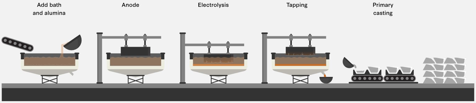
The process is the sole commercial route to primary aluminium metal, consuming approximately 2 tonnes of alumina and 0.45 tonnes of carbon anode per tonne of aluminium produced, along with approximately 13–15 MWh of electrical energy per tonne — making it one of the most electricity-intensive industrial processes in the world.
Chemistry
Cathode reaction (reduction):
Al3+ + 3 e− → Al (liquid)
Anode reaction (oxidation at carbon anode):
C + 2 O2− → CO2 + 4 e−
Overall cell reaction:
2 Al2O3 + 3 C → 4 Al + 3 CO2
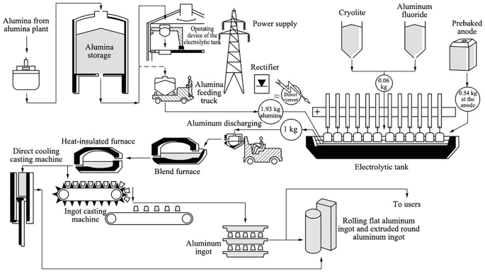
Figure 2 — Schematic process flow of the Hall-Héroult Process (source)
The cryolite electrolyte (Na3AlF6) does not participate in the overall reaction but serves as the solvent for alumina — it dissolves Al2O3 at concentrations of 2–8 wt%, lowers the melting point of the bath to ~950°C (pure cryolite melts at 1,012°C), and provides adequate electrical conductivity. Additives including aluminium fluoride (AlF3), calcium fluoride (CaF2) and lithium fluoride (LiF) are used to tune bath temperature, density and conductivity. The dissolved alumina concentration is carefully maintained in a narrow operating window — too high causes sludge formation; too low causes anode effect (a disruptive high-voltage arc event associated with perfluorocarbon (PFC) emissions).
Process Steps, Conditions & Parameters
Step 1 — Alumina Feed Preparation
SGA (smelter-grade alumina) from the Bayer process is received, stored and fed continuously or semi-continuously to the electrolytic cells via point feeders (automated alumina dispensers). Alumina must meet strict specifications for particle size, surface area, α-Al2O3 content and moisture to ensure good dissolution and avoid crust formation.
| Parameter |
Value |
| Al2O3 purity |
≥98.5% |
| Moisture content |
<0.5% |
| α-Al2O3 content |
5–25% (balance γ-Al2O3) |
| Feed rate control |
Automated point feeders, demand-controlled |
Figure 2 — Schematic process flow of the Hall-Héroult Process (source)

Step 2 — Electrolytic Reduction (The Pot)
The core of the process is the electrolytic cell (pot) — a rectangular steel shell lined with carbon/graphite cathode blocks and refractory insulation. The molten bath fills the cell and is covered by a solidified crust of bath material and alumina. The carbon anodes (either Söderberg continuous self-baking anodes or prebaked carbon anodes) are suspended from an anode beam into the bath from above.
Figure 3 — Hall-Héroult electrolytic cell (source)
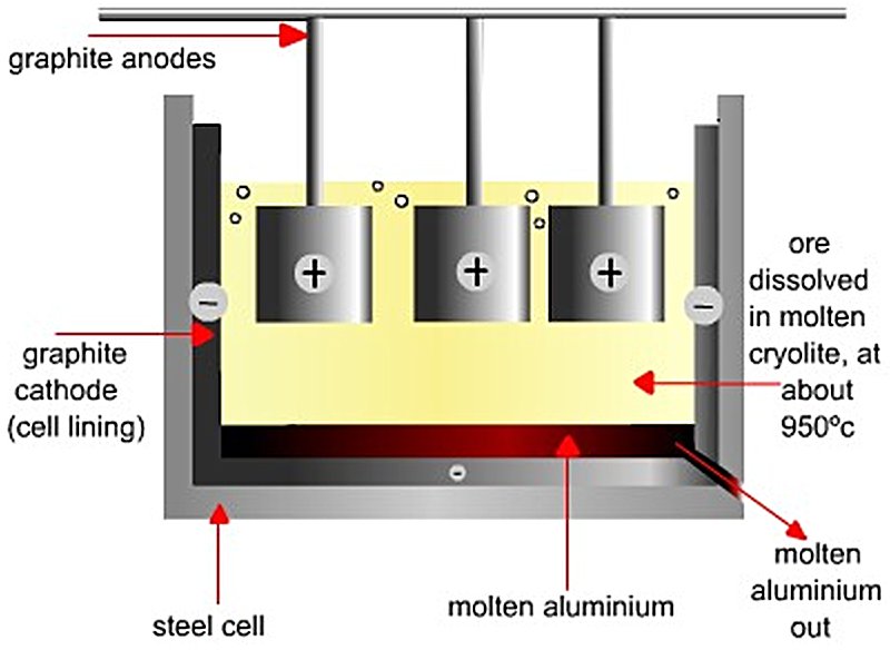
Direct current enters via the anodes, passes through the molten bath, and exits via the cathode lining at the base. Liquid aluminium, being denser than the bath, collects as a liquid metal pad on the cathode floor and is protected by it from re-oxidation.
| Parameter |
Value |
| Bath temperature |
950–980°C |
| Cell voltage |
3.9–4.5 V (thermodynamic minimum ~1.2 V) |
| Line current |
150,000–600,000 A (150–600 kA) per cell |
| Alumina concentration in bath |
2–5 wt% |
| Bath ratio (NaF/AlF3 molar) |
2.2–2.4 |
| Interpolar distance (ACD) |
4–5 cm |
| Current efficiency |
92–96% |
| Specific energy consumption |
13–15 MWh/t Al |
| Carbon anode consumption |
~420–450 kg/t Al |
| Cell (pot) life |
5–10 years before relining |
Step 3 — Metal Tapping
Liquid aluminium (typically ~99.7% purity) is tapped (siphoned or vacuum-lifted) from the pot every 24–48 hours using a crucible-based vacuum tapping system. Metal is transferred in large crucibles to the cast house.
Step 4 — Anode Change
In prebaked anode (PBA) technology, individual carbon anode blocks (~1,000–1,500 kg each) are consumed over approximately 24–28 days and must be replaced regularly. Each pot carries 18–40 anode blocks simultaneously at different stages of consumption. Anode stubs (spent anode butts) are recovered and recycled in the anode baking facility.
In Söderberg technology, continuous anode paste is fed from above and bakes in situ using waste heat from the cell — eliminating the separate anode baking plant but producing more PAH (polycyclic aromatic hydrocarbon) emissions. Söderberg technology is being phased out globally.
Step 5 — Gas Treatment (Dry Scrubbing)
Each pot generates HF gas, CO2, CO, SO2 and PFC gases (CF4 and C2F6 during anode effects). These are captured by a hooding and duct system and treated in a dry scrubbing plant where the gases pass through a bed of fresh alumina, which adsorbs the fluoride gases. The fluoride-laden alumina is then fed back to the pots as part of the regular feed — simultaneously treating the gas stream and recovering fluoride back into the process. Residual gases pass through bag filters before emission.
Step 6 — Casting
Liquid aluminium from tapping crucibles is transferred to the cast house, where it is:
- Held in holding/melting furnaces (gas-fired)
- Alloyed as required by adding silicon, magnesium, copper, manganese, etc.
- Degassed (nitrogen/argon purging or rotary degassing) to remove dissolved hydrogen
- Filtered through ceramic foam filters to remove inclusions
- Cast into standard product forms: T-bar ingots, sow ingots, rolling slabs, extrusion billets or wire rod via DC (direct chill) casting
Key Equipment & Devices
| Equipment |
Function |
Key Specifications |
| Electrolytic Pots (Cells) |
Core electrolysis vessel |
Steel shell, carbon-lined cathode, 150–600 kA current |
| Prebaked Carbon Anodes |
Consumable oxidation electrode |
~1,000–1,500 kg blocks;
replaced every 24–28 days |
| Söderberg Anode System |
Continuous self-baking anode |
Paste fed from top;
being phased out |
| Anode Beam / Busbar |
Current distribution and anode positioning |
Hydraulically adjusted
for ACD control |
| Point Feeders |
Automated alumina dosing into bath |
Demand-controlled;
typically 2–4 per pot |
| Potline DC Rectifiers |
Convert AC grid power to high-amperage DC |
Thyristor rectifier stations;
150–600 kA |
| Busbar Network |
Inter-cell current conductors |
Aluminium/copper busbars; precisely engineered for
magnetic field compensation |
| Vacuum Tapping Crucibles |
Remove liquid metal
from pots |
3–5 t capacity; transported
by overhead crane |
| Pot Tending Machines (PTM) |
Crust breaking, anode change, metal tapping |
Rail-mounted; semi-
or fully automated |
| Gas Collection Hooding |
Capture pot gases
(HF, CO2, PFC) |
Sealed pot covers
with suction ducting |
| Dry Scrubbers (Alumina Adsorbers) |
Remove fluoride
from pot gases |
Countercurrent fluoride adsorption on alumina |
| Bag Filters |
Final particulate removal from exhaust gas |
High-efficiency
fabric filters |
| Anode Baking Furnace |
Bake green carbon anodes to prebaked state |
Ring furnaces;
~1,100–1,150°C |
| Rodding Shop |
Attach cast iron stubs
to baked anodes |
Thimble casting;
mechanical assembly |
| Holding/Melting Furnaces |
Hold and alloy liquid metal in cast house |
Gas-fired tilting furnaces;
30–80 t |
| DC Casting Equipment |
Solidify metal into billets/slabs/ingots |
Direct-chill (DC)
casting tables |
| Degassing Units |
Remove H2 from
liquid metal |
Rotary impeller degassing (SNIF, Hycast) |
Process Efficiency & Economics
Material Efficiency
- Alumina consumption: ~1.93 t Al2O3 per tonne of aluminium (theoretical 1.89 t/t)
- Carbon anode consumption: ~420–450 kg/t Al (prebaked); ~500–550 kg/t Al (Söderberg)
- Cryolite/fluoride consumption: ~20–30 kg AlF3/t Al (make-up only, as the bath is recycled)
- Current efficiency: 92–96% in modern high-amperage cells
Energy
- Specific electrical energy: 13–15 MWh/t Al at modern smelters; best-in-class cells achieve ~12.9 MWh/t Al
- Theoretical thermodynamic minimum is ~6.3 MWh/t Al; the gap reflects ohmic heating, overpotentials and heat losses
- Electrical energy typically represents 25–40% of total aluminium production cost, making power price the dominant variable cost driver
- Smelters are therefore located near low-cost hydropower (Iceland, Norway, Canada, Brazil, Mozambique) or low-cost coal power (China, India, Australia, Middle East)
Economics
- Operating cost (cash cost): approximately USD 1,400–2,200/t Al depending heavily on power cost and region (2024 range)
- Capital cost: a new greenfield smelter of 500 ktpa capacity costs USD 3–5 billion
- Break-even aluminium price: approximately USD 1,500–1,800/t for low-cost hydro-powered smelters; USD 2,000–2,400/t for coal-powered smelters
- LME aluminium price: USD 2,200–2,700/t in 2024–2025
- Chinese smelters account for approximately 60% of global primary aluminium production (~70 Mt/yr global in 2024)
Global Market Deployments
| Country / Region |
Key Smelters / Operators |
Notes |
| China |
Chalco, State Power Investment Corp, Xinfa, Hongqiao |
~40 Mt/yr; world's dominant producer; largely coal-powered |
| India |
Hindalco (Hirakud, Mahan), Vedanta (BALCO, Jharsuguda) |
Rapidly expanding;
coal-powered |
| Russia |
Rusal (Bratsk, Krasnoyarsk, Sayanogorsk) |
Major hydro-powered smelters
in Siberia; ~3.9 Mt/yr |
| Canada |
Rio Tinto Alcan (Alma, Kitimat), Alcoa (Baie-Comeau) |
Hydro-powered;
~3 Mt/yr |
| UAE / Bahrain |
EGA (Al Taweelah, Jebel Ali), Alba (Bahrain) |
Gas-powered; among world's largest single smelters |
| Norway / Iceland |
Hydro (Årdal, Husnes), ISAL, INAL |
Hydropower-based; lowest
carbon intensity globally |
| Australia |
Alcoa (Portland), South32 (Worsley-linked) |
Grid-powered; under decarbonisation pressure |
| Brazil |
Albras (Barcarena), CBA |
Hydro-powered; low-cost |
| USA |
Century Aluminium, Alcoa (few surviving) |
Largely shuttered
due to power costs |
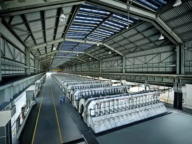
Figure 4 — Prebake potroom at EGA’s Jebel Ali site (Source)
Technology Licensors & Cell Technology Providers
Unlike the Bayer process, cell technology in Hall–Héroult smelting is proprietary and actively licensed — the key competitive differentiator between smelters is the amperage, energy efficiency and productivity of the cell design (referred to by "AP" — Amperage + Pot — designations):
| Licensor |
Cell Technology |
Key Features |
Rio Tinto Alcan
(AP Technology) |
AP40, AP60, AP60+, AP5X |
Industry-leading 600 kA class cells; AP5X targets >500 kA |
| Alcoa |
PFPB (point-fed prebaked), various proprietary cells |
Alcoa 22, Alcoa 300 series;
A-997 anode design |
| Norsk Hydro |
HAL230, HAL250, HAL300 |
Optimised for Nordic hydropower conditions |
| EGA (Emirates Global Aluminium) |
DX, DX+, DX+ Ultra |
Proprietary UAE-developed technology; DX+ Ultra
at ~13.5 MWh/t Al |
| Rusal |
RA-300, RA-400, RA-550 |
Russian proprietary
high-amperage cells |
| China Aluminium (Chalco) / NERIN |
Various 400–600 kA domestic designs |
Predominantly used
in Chinese smelters |
| Outotec / Metso |
Anode baking furnace technology, gas treatment systems |
Key equipment supplier;
not cell licensor |
| Fives (France) |
Anode baking ring furnaces, pot tending machines |
Major equipment
supplier globally |
| Pyrotek |
Degassing, filtering, casting equipment for cast houses |
Widely deployed in
cast houses globally |
Environmental Considerations
The Hall–Héroult process is carbon-intensive by design — the carbon anodes are consumed and oxidised to CO2 as part of the fundamental electrochemistry, generating approximately 1.5–1.7 t CO2/t Al from anode consumption alone, plus indirect emissions from electricity generation (variable by grid carbon intensity, from near-zero at hydro-powered smelters to ~12 t CO2/t Al at coal-powered Chinese smelters).
Perfluorocarbon (PFC) emissions — CF4 and C2F6 generated during anode effect events — are potent greenhouse gases (GWP of 6,500 and 9,200 respectively) and are closely monitored and minimised through anode effect frequency reduction. Fluoride emissions (gaseous HF and particulate) are controlled by the dry scrubbing systems and represent an environmental legacy at older smelters.
The primary long-term decarbonisation strategy is the inert anode — replacing consumable carbon anodes with non-consumable ceramic or metallic anodes, which would change the anode reaction from carbon oxidation to oxygen evolution, eliminating CO2 and PFC emissions from the cell entirely. Elysis (a joint venture between Alcoa and Rio Tinto, backed by Apple and the Canadian government) is the leading commercial programme developing inert anode technology, with industrial-scale demonstration ongoing as of 2025.
References
References are temporarily parked here


