1. Process Context and Purpose
The propane–propylene splitter (P–P splitter, or "C3 splitter") is one of the most demanding distillation duties in the hydrocarbon industry, and a core asset wherever propylene must be separated from propane at high purity. It appears in two principal industrial contexts:
- FCC-based refineries — as the centerpiece of the Propylene Recovery Unit (PRU), recovering olefinic propylene co-produced with propane in the fluid catalytic cracker's off-gas and LPG streams.
- On-purpose propane dehydrogenation (PDH) units — where fresh and recycled propane is catalytically dehydrogenated to propylene, and the splitter closes the loop by separating converted propylene from unconverted propane, which is recycled to extinction.
In FCC service, off-gas and LPG contain substantial propylene — typically 4–8 wt% of fresh feed, and up to 15–20% in petrochemical-mode (PFCC) operation. In PDH service, the splitter processes the full reactor effluent C3 stream, where per-pass propane conversion is only 35–50% (equilibrium-limited, dehydrogenation being endothermic and reversible), so the splitter must handle a much higher recycle propane load relative to propylene product than in FCC service. In both cases, recovering propylene at polymer-grade (99.5–99.9 mol%) or chemical-grade (92–96 mol%) purity requires separating it from propane — two components with a relative volatility of only ~1.08–1.2, one of the most difficult close-boiling separations in the hydrocarbon industry. This demands superfractionation: very tall columns with exceptionally high tray counts, high reflux ratios, and — for energy optimization — heat pump integration.
2. Feed Preparation (upstream of the splitter)
2.1 FCC-derived feed
The splitter feed is the C3 cut recovered from the FCC unsaturated gas plant, after:
2.2 PDH-derived feed
In a PDH unit, the splitter feed is the treated reactor effluent after:
- Compression and quench — reactor effluent (typically low-pressure, high-temperature for endothermic dehydrogenation, catalytic or fluidized-bed depending on licensor) is compressed and cooled.
- Selective hydrogenation — propyne (methylacetylene) formed as a dehydrogenation by-product is hydrogenated back to propylene/propane, since no MAPD source other than the reaction itself exists; impurity levels are generally easier to control than in FCC service because the feed is purpose-grown from near-pure propane.
- Deethanizer (C2–/C3 removal) — hydrogen, methane, ethane/ethylene formed by side-cracking reactions are stripped overhead, leaving an essentially binary C3 stream (propane + propylene) with only trace C2 and C4+, unlike the more complex FCC gas-plant slate.
- Drying — molecular sieve drying to protect against hydrate/ice formation, as in FCC service.
Because PDH feed is not diluted by refinery-wide C3/C4 contaminants and is not constrained by crude slate variability, PDH-fed splitters typically see a cleaner, more consistent binary C3 feed than FCC-fed splitters — but at a materially different split ratio: feed propylene content from a single-pass PDH reactor is commonly only 30–50 mol% (versus 70–90% typical of a high-severity FCC C3 cut), since the bulk of the feed is unconverted propane destined for recycle to extinction back to the reactor section.
3. Superfractionator Configuration
Single-tower vs. two-tower (tandem) design:
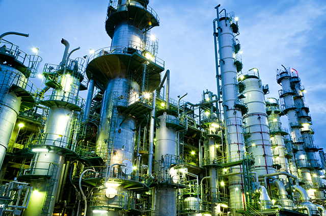
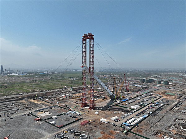
Because propylene/propane separation requires 150–250 theoretical stages, a single tower would be impractically tall (often 90–120 m). Two configurations are used:
- Two towers in series (classic arrangement): the "bottoms" tower and "tops" tower, hydraulically linked — overhead vapor from the bottom tower feeds the base of the top tower; liquid from the top tower base is pumped back as reflux to the bottom tower. Together they function as one 200+ tray column, splitting the height into two manageable vessels.
- Single very tall tower: feasible for smaller capacities or with high-capacity trays; increasingly considered with modern tray technology.
Internals — MD trays:
The towers are equipped with high-capacity multiple-downcomer (MD) trays (a UOP-developed design, also offered as equivalent high-capacity trays by Sulzer, Koch-Glitsch, and others). MD trays feature:
- Multiple downcomers per tray with short weirs, distributing liquid load across the deck
- High active area and vapor capacity — critical because P–P splitters operate at very high reflux ratios (L/D of 8–20:1 in FCC service; often toward the higher end, or higher still, in PDH recycle service given the lower feed propylene concentration) and enormous internal traffic
- Close tray spacing (350–450 mm) enabled by low entrainment, reducing tower height
- Typical installations: 180–240 actual trays total at ~60–75% overall efficiency
Operating conditions
| Parameter |
FCC/PRU service |
PDH service |
| Operating pressure |
16–22 barg (set by cooling water temperature for overhead condensation, or by heat pump balance) |
| Overhead temperature |
40–55 °C (propylene product) |
| Bottom temperature |
50–65 °C (propane) |
| Reflux ratio (L/D) |
8–20 : 1 |
Often higher, reflecting lower feed propylene fraction and full-recycle duty |
| Theoretical stages |
150–250 |
| Relative volatility |
~1.08–1.15 (pressure-dependent;
lower pressure improves α slightly) |
| Feed C3 composition |
70–90% propylene (C2/C4 stripped upstream) |
30–50% propylene (bulk is unconverted propane for recycle) |
| Propylene recovery |
99–99.7% |
4. Heat Pump System (Vapor Recompression)
P–P splitters are among the largest energy consumers in both FCC complexes and PDH units — the reboiler duty is enormous due to the high reflux ratio. Because the overhead vapor (propylene) and bottoms liquid (propane) differ by only ~10–15 °C in temperature, the system is ideally suited to a heat pump (vapor recompression) cycle, which exploits the small temperature lift. This is standard practice in essentially all modern C3 splitters, whether FCC- or PDH-fed, since both share the same narrow-boiling-point challenge.
Configuration — open-cycle heat pump (most common):
- Overhead vapor withdrawal: propylene-rich overhead vapor is drawn from the column top instead of being directly condensed.
- Compression: the vapor is compressed in a centrifugal compressor (single or two-stage, typically motor-driven; large units may exceed 10–20 MW) raising its pressure and saturation temperature by ~20–35 °C.
- Reboiler condensation: the compressed hot vapor is routed to the reboiler exchanger(s), where it condenses, surrendering its latent heat to boil the column bottoms — the heat pump effectively recycles the column's own overhead latent heat into the reboiler.
- Condensate split: the condensed propylene is then flashed/expanded back; a portion returns as reflux to the column top, the balance is withdrawn as propylene product through a trim cooler (or, in PDH service, routed onward to product finishing/storage or directly to a downstream polypropylene unit).
Benefits:
- Eliminates or drastically reduces steam/hot-oil reboiling — energy savings of 60–80% vs. conventional steam-driven reboiler + water-cooled condenser arrangement
- Eliminates the large overhead condenser (the reboiler itself serves as the condenser)
- Utilities reduced to compressor power plus small trim coolers and a small start-up/trim reboiler
- Typical payback of the compressor capital: 1–3 years at historical energy prices
Alternative closed-cycle (external refrigerant) heat pumps are occasionally used but open-cycle (process fluid as the working fluid) dominates because propylene itself is an excellent refrigerant, eliminating an intermediate loop.
5. Product Specifications
| Grade |
Propylene Purity |
Key Impurity Limits |
Use |
| Polymer grade |
≥ 99.5–99.9 mol% |
MAPD < 5 ppm, S < 1 ppm,
C₂ < 500 ppm,
water < 2 ppm |
Polypropylene, acrylates,
acrylonitrile |
| Chemical grade |
92–96 mol% |
Relaxed |
Cumene, oxo-alcohols,
some alkylation |
| Propane bottoms |
≥ 90–95% propane |
Propylene
< 2–5% |
FCC: LPG pool, steam cracker feed.
PDH: recycled to extinction back to the dehydrogenation reactor, with only a small propane purge to manage inert/by-product build-up. |
6. Technology Performance and Considerations
- Recovery: 99%+ of feed propylene recovered at product purity
- Energy: heat-pumped designs achieve specific energy consumption of roughly 0.15–0.25 MW per t/h propylene (vs. 3–5× higher steam-equivalent for conventional reboiling)
- Safety: large propylene/propane inventory in tall towers requires rigorous relief and flare design; compressor sealing (dry gas seals) critical; MD tray fouling minimal in clean C3 service
- Capacity: single-train P–P splitters up to ~600–800 KTPA propylene are in operation. PFCC complexes with very high propylene yields may require two parallel splitter trains — as contemplated in designs with 20% propylene yield on fresh feed. World-scale PDH units are typically sized to match a single dehydrogenation train (commonly 450–750 KTPA propylene), with the splitter sized to the full recycle-inclusive C3 traffic rather than to net propylene production alone — meaning the column's internal vapor/liquid loading, and hence its diameter and reboiler/compressor duty, can be large relative to its net propylene make
7. Role in the Integrated Complex
In a petrochemical-maximizing refinery where the PFCC is designed for ~20% propylene yield — the heat-pumped P–P superfractionator is a cornerstone asset: it converts cracked C₃s into polymer-grade propylene feeding the polypropylene and acrylates trains, while the propane bottoms, fully saturated and sweet, join the SR LPG pool as premium steam cracker feed. The heat pump integration aligns with the complex's energy self-sufficiency philosophy, minimizing steam demand on the gasification block.