Membrane Electrolysis
An advanced description of the membrane cell technology is provided in the Technology Type description.
The membrane cell is a diaphragm cell with an improved diaphragm called a ‘membrane’, which has been modified to include anionic groups to act as an
ion exchange membrane, so that the diaphragm is a permselective ion-exchange membrane. This membrane inhibits the passage of chlorine ions (negatively charged), but allows sodium ions (positively charged) to move through freely (Fig. 1)[1,2].
Today’s membranes are made of a perfluorosulfonate polymer layer, a polytetrafluoroethylene (PTFE) reinforcing fabric, and a perfluorocarboxylate polymer, bonded together This combination allows for low electrical resistivity and for low caustic back migration, which ultimately creates a more efficient and productive system[1].
Figure 1 - Schematic view of chlorine electrolysis membrane cell[3]
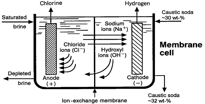
In this process, sodium brine or potassium brine is fed to the cell and distributed equally throughout the anode compartments while water flows into the cathode compartments. The electrolysis reactions in this process are the same as they are in the diaphragm cell process[1].
As the brine is depleted it overflows with chlorine gas into an anolyte header and the caustic soda that is produced overflows with hydrogen gas into a catholyte header[1].
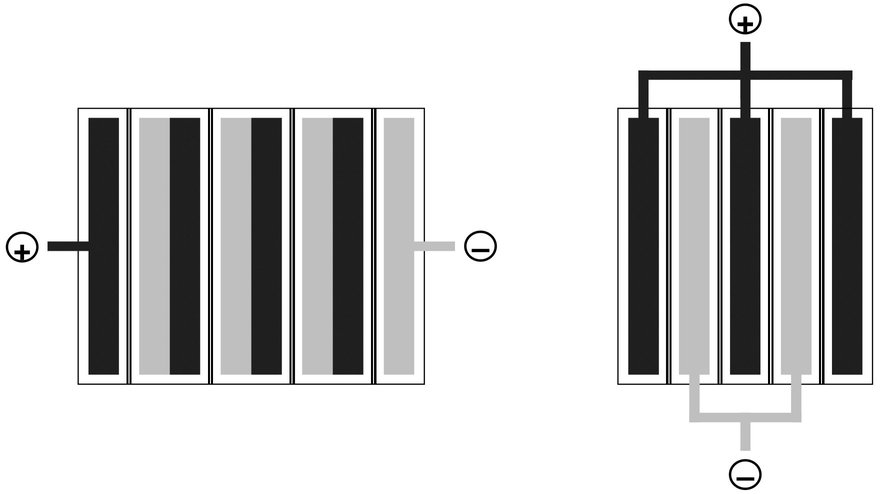
Membrane electrolysers containing a multitude of cells are classified as either monopolar or bipolar, referring to the electrolyser construction or assembly (Fig. 2)[3]:
- In a bipolar arrangement, the elements are connected in series with a resultant low current and high voltage (Kirchhoff's circuit laws). The cathode of a cell is connected directly to the anode of the adjacent cell.
- In the monopolar arrangement, all anodes and cathodes are connected in parallel, forming an electrolyser with a high current and low voltage. The current has to be connected to every single anodic and cathodic element, while in a bipolar electrolyser the power supply is connected only to the end part of the electrolyser. Due to the long current path, ohmic losses in monopolar electrolysers are much higher than in equivalent bipolar electrolysers, leading to increased energy consumption
Figure 2 - Monopolar and bipolar electrolysers[3]
| Bipolar Electrolyser |
Monopolar electrolyser |
 |
Process Configuration
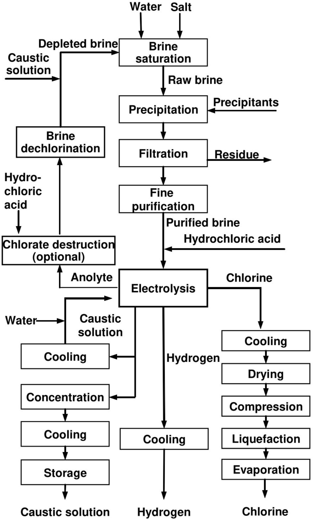
A typical membrane cell chlor-alkali process schematics is shown in Fig. 2.
Figure 3 - Typical Block Flow Diagram of a complete chlor-alkali membrane cell process[3].
Brine System
- Brine Preparation
When solid salt (NaCl, KCl) is the raw material, a dissolving operation becomes necessary, and this may be carried out in open or closed vessels. The water and/or depleted brine (spent NaCl brine, spent KCl brine) can be sprayed onto the salt or introduced at the base of the saturator for progressive saturation when running through it. In the latter case, the saturated brine overflows the equipment at the top. Modern saturators are closed vessels to reduce emissions of salt spray or mist. In case of NaCl, concentrations in the saturated brine reach values of 310–315 g/l[3].
- Brine Purification
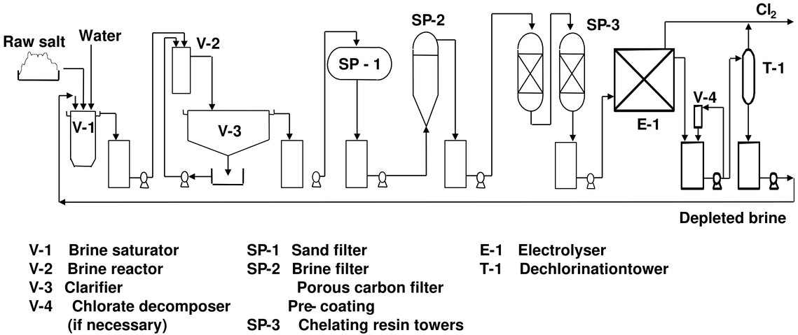
Brine purification is detailed in Fig. 4[3].
The initial stage of purification uses sodium carbonate and sodium hydroxide to precipitate calcium and magnesium ions as calcium carbonate (CaCO3) and magnesium hydroxide (Mg(OH)2). Metals (iron, titanium, molybdenum, nickel, chromium, vanadium, tungsten) may also precipitate as hydroxide during this operation. The usual way to reduce the concentrations of metals is to specify maximum concentration values in the purchase specifications for the salt. Sodium sulphate can be controlled by adding calcium chloride (CaCl2) or barium salts (BaCO3 or BaCl2) to remove sulphate anions by the precipitation of calcium sulphate (CaSO4) or barium sulphate (BaSO4). The precipitation of barium sulphate can take place simultaneously with the precipitation of calcium carbonate and magnesium hydroxide, whereas the precipitation of calcium sulphate requires a separate vessel[3].
Figure 4 - Flow diagram of a possible layout for the brine system used in the membrane cell technique[3]
When vacuum salt is used as raw material, only a part of the brine stream might be treated in the primary purification unit, while the total stream is usually treated when using other salt types. Some plants using vacuum salt omit primary brine purification completely. The precipitated impurities are removed by sedimentation, filtration or a combination of both. The separated filter cake is generally concentrated to 50–60 % solids content in filter presses, rotary drum vacuum filters or centrifuges before disposal. The sulphate content can also be reduced without the use of expensive barium salts by purging a part of the brine, by cooling the brine stream and crystallising Na2SO4·10 H2O, by precipitating the double salt Na2SO4·CaSO4, by ion exchange, or by nanofiltration combined with purging of the brine[3].
To maintain the high performance of the ion-exchange membrane, the feed brine must be purified to a greater degree than in the mercury or diaphragm cell techniques. The precipitation step alone is not enough to reduce the levels of calcium and magnesium, and additional softening is thus required. Secondary brine purification generally consists of polishing filtration and brine softening in an ion-exchange unit[3].
- Brine Dechlorination and Resaturation
Membrane cell plants usually operate with brine recirculation and resaturation. In recirculation circuits, the depleted brine leaving the membrane electrolysers is first totally dechlorinated. For this purpose, the brine containing 0.4–1 g/l of dissolved chlorine is generally acidified to pH 2–2.5 and sent to an air-blown packed column or sprayed into a vacuum system of 50–60 kPa to extract the majority of the dissolved chlorine to a residual concentration of 10–30 mg/l. Complete dechlorination is achieved by passing the brine through an activated carbon bed, by catalytic reduction, or by using chemical reducing agents such as sulphite. The chlorine-containing vapours are subsequently fed back to the raw chlorine collecting unit or directed to the chlorine absorption unit. The water that evaporates from the dechlorinated brine is condensed in a cooler. The condensate can be sent back to the brine system or chemically dechlorinated[3].
If the saturation is carried out with impure salt (followed by a primary purification step of the total brine flow), the pH of the dechlorinated brine is then brought to an alkaline value with caustic soda to reduce the solubilisation of impurities from the salt. If the saturation is carried out with pure salt (with subsequent primary purification on a small part of the flow), there is no alkalisation step prior to the resaturation (only in the purification phase). Brine resaturation using solid salt is described in Section 1 above. In the case of membrane cell plants operating with solution-mined brine, brine resaturation is achieved by evaporation. During this step, sodium sulphate precipitates and can be recovered, purified and used for other purposes[3].
- Chlorate Destruction
In order to reduce the build-up of chlorate in the brine circuit, which could have negative effects on the ion-exchange resins, the caustic quality, and on emissions to the environment, some membrane cell plants operate a chlorate destruction unit prior to the dechlorination. Techniques include the reduction of chlorate to chlorine with hydrochloric acid at temperatures higher than 85 °C and the catalytic reduction of chlorate to chloride with hydrogen[3].
Chlorine processing, storage and handling
Generally, before the chlorine can be used, it goes through a series of processes for cooling, cleaning, drying, compression and liquefaction as detailed below[3].
- Cooling
In the primary cooling process, the total volume of gas to be handled is reduced and a large amount of moisture is condensed. Cooling is accomplished in one or several stages with water, brine or other fluids. Care is taken to avoid excessive cooling because, at around 10 ºC, chlorine can combine with water to form a solid material known as chlorine hydrate (Cl2 · n H2O; n = 7–8). Maintaining temperatures above 15 °C prevents blockages in the process equipment.
Two methods are most frequently used to cool chlorine gas:
- One method is indirect cooling through a titanium surface (usually in a single-pass vertical shell-and-tube heat exchanger). The resultant condensate is fed back into the brine system. Indirect cooling can be carried out in once-through, open-recirculating, or closed-loop systems.
- Another method is direct cooling with water (or brine or other fluids). The chlorine gas is cooled by passing it directly into the bottom of a tower. Water is sprayed from the top and flows countercurrently to the chlorine. The cooling water is generally free of traces of ammonium salts, to avoid the formation of nitrogen trichloride. Direct cooling is usually carried out in closed-loop systems.
- Cleaning of wet chlorine
Following primary cooling, water droplets and impurities such as brine mist are removed mechanically by using special filters with glass wool fillings or porous quartz granules, or by means of an electrostatic precipitator. Chlorine is then passed to the drying towers
- Drying
Chlorine from the cooling system is more or less saturated with water vapour. The water content is typically 1–3 vol-%. This must be reduced in order to avoid downstream corrosion and to minimise the formation of hydrates. The drying of chlorine is carried out almost exclusively with concentrated sulphuric acid (96–98 wt-%) in countercurrent contact towers in two to six stages, which reduce the moisture content to less than 20 mg/m3.
The remaining moisture content depends on the temperature and concentration of the sulphuric acid in the last drying stage. For low-temperature liquefaction, a lower moisture content is required, which can be achieved by adding more equilibrium stages to the drying towers or by using molecular sieves to levels of 3–9 mg/m3.
The number of stages is usually increased to lower the final strength of the spent sulphuric acid. For example, three stages are needed to reach a spent acid concentration of 50–65 wt-% while six stages are needed for a final concentration of 30–40 wt-%. The heat liberated during dilution of the circulating acid is removed by titanium heat exchangers, and the spent acid is dechlorinated chemically or by stripping. The concentration of the spent acid depends on the number of drying stages and the further potential use or method of disposal. In some cases, the acid is reconcentrated to 96 wt-% by heating it under vacuum and then it is subsequently recirculated. Sometimes the acid is sold or used for other purposes. Rarely, it becomes waste.
- Cleaning of Dry Chloride
When leaving the top of the drying tower, dry chlorine passes through high efficiency demisters or a packed bed to prevent the entrainment of sulphuric acid droplets.
Further potential cleaning steps after chlorine drying include:
- adsorption on carbon beds to remove organic impurities;
- absorption-desorption using a suitable solvent such as carbon tetrachloride to remove;
- nitrogen trichloride and organic impurities;
- scrubbing with concentrated hydrochloric acid to remove nitrogen trichloride;
- scrubbing with liquid chlorine to remove nitrogen trichloride, organic impurities, carbon dioxide and bromine;
- irradiation with UV to destroy nitrogen trichloride and hydrogen.
- Chlorine Gas Compression
After drying and potential further cleaning, chlorine gas may be compressed by a variety of compressors, depending on the throughput and the desired pressure. Because of heat build-up from compression, multi-stage units with coolers between stages are usually necessary. Dry chlorine at high temperatures can react spontaneously and uncontrollably with iron. Chlorine temperatures are therefore usually kept below 120 °C.
- Chlorine Gas Liquifaction
Liquefaction can be accomplished at different pressure and temperature levels: at ambient temperature and high pressure (for example 18 ºC and 7–12 bar), at low temperature and low pressure (for example -35 ºC and 1 bar) or any other intermediate combination of temperature and pressure. The liquefaction yield is typically limited to 90–95 % in a single-stage installation, as hydrogen is concentrated in the residual gas and its concentration needs to be kept below the lower
explosive limit. Higher yields of up to 99.8 % can be achieved by multi-stage liquefaction. Typically, small volume liquefiers which are protected against explosions are used after primary liquefaction, and inert gas is added to keep the mixture below the lower explosive limit. Another possibility is to remove hydrogen from the system by reaction with chlorine gas in a column, yielding hydrogen chloride which can be recovered in a hydrochloric acid unit. The remaining chlorine gas can then be safely further condensed. This solution can be chosen if hydrochloric acid is a saleable product or if it can be used as a feedstock for downstream production, such as for ferric chloride.
The residual chlorine in the tail gas can be used to produce hypochlorite, iron(III) chloride or hydrochloric acid. The residual chlorine which cannot be valorised is then led to the chlorine absorption unit. In some cases, it is recovered by an absorption-desorption process with carbon tetrachloride. The latter has the disadvantage of using a toxic substance with a high ozone depletion and global warming potential.
- Liquid Chlorine Handling and Storage
Liquefied chlorine is stored at ambient or low temperature. The pressure corresponds to the vapour pressure of the liquefied chlorine at the temperature in the storage tank. Pressure storage at ambient temperatures (~ 7 bar at 20 °C) has advantages of simplicity of operation, ease of visual external inspections, as well as lower energy and investment costs. Low-pressure storage operating around the boiling point of liquid chlorine (-34 °C) requires more complex infrastructure, particular safety measures and higher energy costs.
Within a plant and over distances of several kilometres, chlorine can be transported by pipelines, either as a gas or a liquid. The liquid chlorine from the bulk tank can be used as a feedstock for on-site processes or loaded into containers, or road or rail tankers.
- Vaporisation of Liquid Chlorine
Liquid chlorine is usually vaporised prior to use. The easiest option is to use ambient heat by which approximately 5 kg of chlorine per hour and square metre of container surface can be vaporised. For higher flowrates, it is necessary to use a chlorine vaporiser.
Caustic processing, storage and handling
The caustic soda solution from membrane cell is usually concentrated to 50 wt-% by evaporation before storage. Steam is used as the source of evaporative energy, which is normally achieved in two or three stages using either plate or shell-and-tube evaporators. The number of stages depends on factors such as plant size and the cost of steam[3].
The caustic soda from membrane cells is of high quality, although the caustic soda produced (usually around 32 wt-% NaOH) needs to be concentrated to 50 wt-% NaOH to be traded as a commodity. The NaCl content of the membrane-cell caustic soda lies between 20 and 100 ppmw (in 100 % NaOH). In some plants, the caustic soda is further concentrated to a 73 wt-% solution and to solid caustic prills or flakes with a water content of < 0.5–1.5 wt-%, using multi-effect evaporators[3].
Tanks are usually included in procedures to prevent overflow or spillage of caustic soda. Dissolved hydrogen gas can be released into the vapour space above the liquid in storage tanks. Tanks are normally vented from the highest point[3].
Hydrogen processing, storage and handling
Hydrogen leaving the cells is highly concentrated (> 99.9 vol-%) and normally cooled to remove water vapour, sodium hydroxide and salt, which is usually carried out by one or more large heat exchangers. Some uses of hydrogen require additional removal of traces of oxygen, which may be achieved by reacting the oxygen with some of the hydrogen over a platinum catalyst. The solution of condensed salt water and sodium hydroxide is recycled to produce caustic, as brine make-up or is treated with other waste water streams[3].
Hydrogen may be distributed to users using booster fans or fed to the main compression plant, which usually comprises a number of compressors and a gas holder (surge chamber). The hydrogen gas holder is incorporated into the system to minimise fluctuations in gas pressure from the primary stage. The hydrogen product gas stream is always kept pressurised to avoid the ingress of air[3].
The hydrogen sold to distributors is usually compressed at pressures higher than 100 bar and is injected into a pipeline network. Otherwise, the hydrogen is transported in dedicated tank lorries or in steel bottles at pressures of up to 300 bar. For these high pressures, the gas is further dried and traces of oxygen are usually removed[3].
Chlorine Absorption Unit
Every chlor-alkali plant generates waste gases consisting of N2, O2, H2, CO2 and 1–8 % of the original chlorine produced. Although the quality of these waste gases is usually insufficient for the main chlorine uses, the chlorine therein still represents a certain market value and is often used for the synthesis of bleach (sodium hypochlorite), hydrochloric acid, iron trichloride, chlorinated hydrocarbons or sulphur monochloride. Most common is the production of bleach in a chlorine absorption unit. Irrespective of the use of the residual chlorine, the absorption of chlorine in caustic solution usually represents the last step before waste gas is released to the atmosphere[3].
The purpose of a typical chlorine absorption system is twofold[3]:
- To continuously absorb chlorine gas arising in streams such as tail gas from liquefaction, air blown from the dechlorination of waste brine or chlorine condensate, or from wet and dry maintenance headers. Up to 5 % but normally less than 1 % of the plant production is absorbed in this way.
- To absorb the full cell room production during an emergency for an adequate period to enable corrective measures to be taken or the plant to be shut down in a safe manner. Gravity-fed head tanks or pumps supplied with backup power supplies may be used to give increased reliability and operation under power failure conditions.
The aforementioned purposes can be achieved by using one or several systems, usually composed of several absorption units placed in series or in parallel to ensure a high level of availability by redundancy. Some additional equipment is often installed as a backup. Packed towers and/or ejector systems are usually used in the chlorine absorption unit[3].
References
- Jedidiah Crook & Aliyar Mousavi (2016) The chlor-alkali process: A review of history and pollution, Environmental Forensics, 17:3, 211-217, DOI: 10.1080/15275922.2016.1177755
- SYNOPSIS CHEMITECH, Chlor Alkali Plant.
- T. Brinkmann et al. Best Available Techniques (BAT) Reference Document for the Production of Chlor-alkali. Industrial Emissions Directive 2010/75/EU. EUR 26844. Luxembourg: Publications Office of the European Union; 2014. JRC91156.