Process Summary
Ionikylation is Composite Ionic Liquid (CIL) alkylation process that produces high octane gasoline constituents from refinery streams.[1] CIL catalyzed isobutane alkylation is a non-hazardous and environmentally friendly process. It has a built-in catalyst regeneration system and can selectively produce high-value alkylate products, thereby overcoming the issues associated with both solid acids and non-composite ionic liquid catalysts.[2] Well Resources Inc. is a licensor of the process..[3]
The key process highlights for Ionikylation include:.[3]
- Inherently safe catalyst;
- Enhanced performance measurements: high activity, high selectivity, no acid runaway reaction;
- Non-corrosive system: carbon steel for materials of construction;
- Integrated catalyst regeneration.
CIL Catalysts
The use of solid acids has been explored as a less hazardous alternative to traditional alkylation catalysts. However, rapid deactivation and difficulty in regenerating spent catalyst remain obstacles. Non-hazardous ionic liquid catalysts, such as acidic chloroaluminate, are also an option but while conventional ionic liquids can overcome obstacles associated with solid acid catalysts, they exhibit low yield and selectivity in producing desirable alkylate products.[2]
The key to the Ionikylation process is the proprietary CIL catalyst, which is a specially formulated, non-volatile, liquid salt material that replaces traditional acid catalysts. CIL refers to 'Chloroaluminate Ionic Liquid' meaning any ionic liquid that contains the tetrachloroaluminate anion. The CIL catalyst is fine-tuned to have high selectivity towards producing the most valuable high-octane gasoline constituents while minimizing the production of undesirable by-products such as acid-soluble oil (Fig. 1).[3]
Figure 1 - The Ionikylation Advantage.[3]
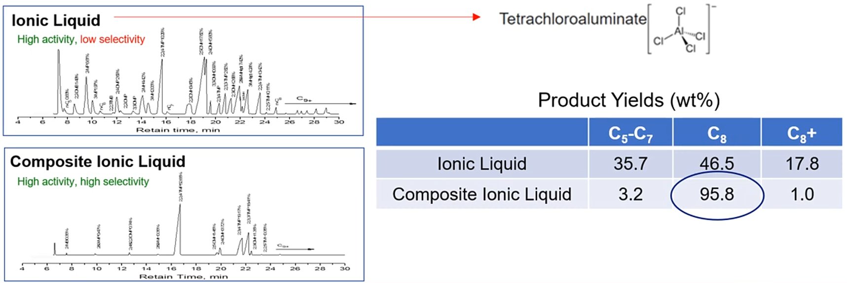
The alkylate C5–C7, C8, and C9+ compositions derived from the conventional acidic chloroaluminate ionic liquid catalyst were 35.7%, 46.5% and 17.8%, respectively, whereas CIL catalyst produced alkylate with compositions of 3.2%, 95.8% and 1%, respectively. The comparison reveals that CIL catalyst has higher selectivity and reactivity for desirable alkylation products, namely TMPs (Fig. 1).[2]
The CIL-catalyzed alkylation is very much stoichiometric, and the performance of the process can be reasonable predicted based on feedstock analysis. n-Paraffins are non-reactive in the Ionikylation process, and it is recommended to have excess isobutane in the feed to ensure complete conversion of the olefins. Propene will be alkylated with isobutane up to C7. C4 olefins will be alkylated with isobutane up to C8, C5 olefins will be alkylated up to C9, and so on.[3,4]
About Composiite Ionic Liquid (CIL):[3]
- Liquid Salt;
- Non-Corrosive;
- Vapor pressure: ~0;
- Density: 1.35 - 1.5 g/cm3;
- Viscosity: 50 - 60 mm2/s (@ 20°C);
- Decomposition temperature: 200°C;
- Freezing point: 3.8°C, -20°C in presence of hydrocarbon.
Process Design
Process Flow Diagram
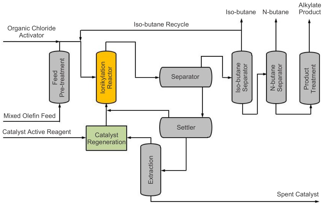
The commercial CIL catalyzed iso-butane alkylation process is characterized by five subprocesses as sown in the process flow diagram in Fig. 2 [1] : feed pre-treatment, reaction, product separation, product treatment, and catalyst regeneration.[2,3]
- The first step in any alkylation process is to pre-treat the feed so that it becomes compatible with the reaction system. In this configuration, plant-derived isobutane is first hydrotreated to remove key contaminents such as sulfur, water, and oxygenates.
- Once treated, the feed is sent to the reactor, where it makes contact with a dense circulating homogeneous CIL catalyst that facilitates the alkylation reaction and the formation of alkylate.
- Afterward a series of settlers where gravity separation is used to differentiate alkylate and light ends from the heavier catalyst. The alkylate and light ends are sent to a fractionator, which further separates the components and recycles unconverted isobutane.
- Catalyst from the first settler is sent through a series of additional settlers and extractors, where a small amount of spent catalyst fines and other solids are ultimately removed (shown at the bottom of the flow diagram). The spent catalyst from the extraction is in the form of a benign solid.
- At the catalyst regeneration unit, makeup active reagents are added to the main quantity of recovered catalyst to offset the spent catalyst removals. Regenerated catalyst is then routed back to the reactor, and an organic chloride compound is injected to supplement the catalyst activity.
Figure 2 - Ionikylation Process Flow Diagram.[1]
Process flexibility
In a base case scenario, Ionikylation will deliver 96 RON alkylate.[4]
In case of a high demand for high octane alkylate, an additional compressor can enhance the alkylate to 98+ RON. The fonction of the compressor is to cool down the iC4 coming back to the reactor. Lowering the reaction temperature in its turn increases the selectivity.
Alternatively, a product fractionator can separate the 96 RON alkylate into alkylate chemicals:
- C7 solvent
- C8 100+ RON alkylate
- C9 solvent.
Retrofit equipment required
Regardless of which process is converted to the Ionikylation process, the minimum equipment required will include the Ionikylation reactor and catalyst regeneration system, as they're unique to the process. In addition, depending on the mechanical Integrity of the existing equipment, a new product fractionator may or may not be required.[3]
For revamping a sulfuric acid system, much of the existing cooling system may be reused. But for revamping an HF alkylation system, which typically doesn't have additional cooling, refrigeration might only be a consideration if an end user intends to produce even higher quality alkylate. But by all means, the inclusion of a dedicated cooling system is not required.[3]
Retrofit equipment required:[3]
- HF alkylation to Ionikylation:
- Ionikylation reactor.
- Catalyst regeneration system.
- Fractionator, depending on integrity of existing equipment.
- Refrigeration, depnding on operator's needs.
- H2SO4 to Ionikylation
- Ionikylation reactor.
- Catalyst regeneration system.
- Fractionator, depending on integrity of existing equipment.
Commercial process performance
Capital and operating costs
Due to the non-corrosive nature of the catalyst, all of the Ionikylation process equipment is manufactured with low-cost carbon steel. The process is also run under mild operating conditions, which lower both the capital and operating costs in relation to the reference technologies.[3]
Operating conditions
The following data presents a snapshot of 2015 commercial operation, obtained during the initial cycle of the first greenfield, 100-metric tonnes/year CIL catalyzed iso-butane alkylation unit:[2]
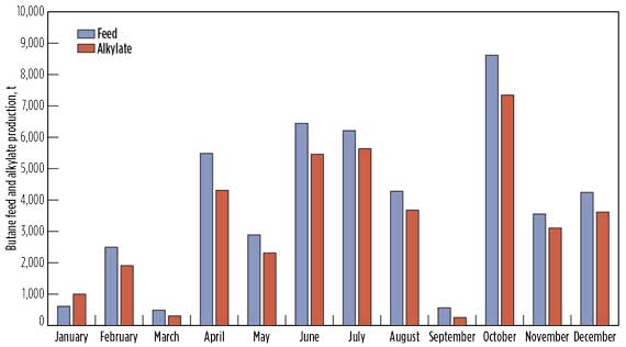
- Fig. 3a shows the monthly volume of butane feed and alkylate produced in the commercial CIL catalyzed alkylation unit throughout 2015. Iso-butane conversion exceeded 90% throughout the run. The data shows that the monthly capacity of the alkylation unit fluctuated over a wide range (10%–90% design capacity), due to the availability of butane feedstock in the spot market. The data also showed that the CIL reactor system is highly flexible to varying feed capacities. On an average annual basis, the alkylation unit operated at 40% of its design processing capacity.
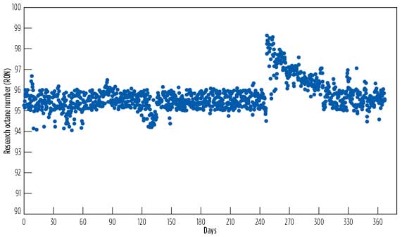
- Fig. 3b shows the research octane number (RON) of CIL-derived alkylate, sampled daily over a one-year period in which the target alkylate RON was set to 95. The data showed that the alkylate RON was relatively constant and often exceeded the set specifications, indicating stable operation. The results showed that the processing capacity variation had no impact on the alkylate RON. On the 250th day, the process operating conditions were adjusted for producing alkylate RON exceeding 98.
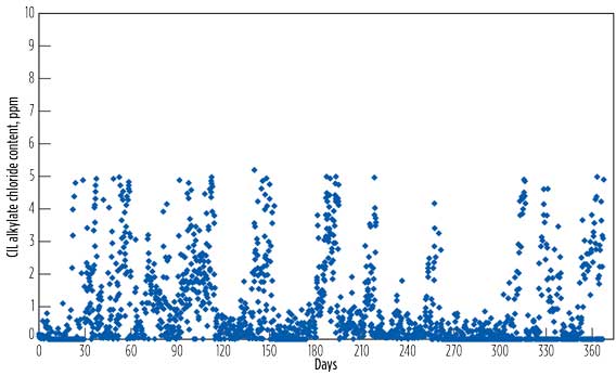
- Fig. 3c shows the chloride content of CIL-derived alkylate, sampled daily over a one-year period in which the alkylate chloride content was set at 5 ppm. The data showed that the majority of the alkylate chloride content was below 2 ppm. Alkylate chloride content is dependent on the volume of chloride introduced into the catalyst regeneration unit.
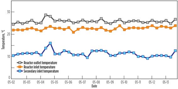
- Fig. 3d shows the CIL reactor inlet and outlet temperatures over a two-week period, recorded at eight-hour intervals. The temperature profiles were relatively constant, indicating stable process operation. The CIL catalyzed iso-butane alkylation reactions are mildly exothermic and are carried out at ambient temperatures and moderate pressures.
Figure 3 - Operational Process Performance[2]
a. Monthly butane feed
& alkylate produced. |
b. CIL-derived
alkylate RON. |
 |
 |
c. CIL-derived alkylate
chloride content. |
d. CIL alkylation
reactor temperatures. |
 |
 |
Energy efficiency
Energy consumption monitored over a one-year period for the CIL catalyzed alkylation process varied from 130 kg EO/t to 160 kg EO/t alkylate produced, which is comparable to the sulfuric acid catalyzed alkylation process.
Byproduct formation
The following table shows the composition of heavy matter (byproduct) that was removed, along with the spent catalyst at the extractor. The amount of heavy matter produced was relatively small. It was discharged from the system once every few days during commercial operation. The byproduct is chemically benign and non-hazardous. It can be easily disposed of and poses no environmental threat.
| Compound |
Dry Basis Weight-% |
| NaCl |
60-75 |
| Al(OH)3 |
10-15 |
| Cu(OH)2 |
5-10 |
| Mineral Oil |
0.1-0.5 |
| SiO2 |
Trace |
| Na2SO4 |
Trace |
| Mg, Ca, Fe |
Trace |
| |
|
Industry Experience
After 8 months of extensive bench-scale laboratory testing in 20023, the CIL catalyzed alkylation process was subjected to a continuous, 4-l/hr alkylate gasoline production pilot run for 60 days.[2]
In 2005, PetroChina conducted the field commercial demonstration of CIL catalyzed alkylation by retrofitting an existing, 65-metric tonnes/year sulfuric acid alkylation unit.[2]
- 2018 - The first greenfield, 2,450 bpd / 100,000 tpy CIL catalyzed alkylation facility was constructed at the Shandong Deyang Chemical Plant in China. It experienced a smooth startup in August 2013. The butane feed used in this facility was a refinery offgas consisting of iso-butane and a small amount of n-butane purchased from nearby refineries.[2]
- 2018 - PetroChina commissioned its first Ionikylation unit at its Harbin refinery, with a processing capacity of 3,700 bpd / 150,000 tpy. The operator has disclosed that the total turnkey capital cost for the project was a mere US$46 million.[3]
- 2019 - PetroChina followed up with another unit sized at 1,225 bpd / 50,000 tpy at its Golmud refinery.[3]
- 2019 - Sinopec commissioned its first of three units each sized at 7,400 bpd / 300,000 tpy. As reported by the operator, the total cost of the turnkey project at the Jiujiang refinery was US$78 million.[3]
- 2020 - The second Sinopec unit with a processing capacity of 7,400 bpd / 300,000 tpy was built at its Wuhan refinery. This unit set a milestone as the worlds first commercial revamp from an existing HF alkylation unit using ionic liquids. This revamped unit was one of two remaining HF alkylation processes in operation in China.[3]
- 2022 - The Sinopec Anqing unit's construction sized at 7,400 bpd / 300,000 tpy was completed in 2020, but due to the coronavirus pandemic, the commissioning was put on hold until Q1 early 2023.[3]
- 2022 - PetroChina constructed another 3,700 bpd / 150,000 tpy unit at its Dagang Refinery and this unit was commissioned in August 2022.[3]
In total, Ionikylation has been commercially proven for almost a decade, across seven units with a total alkylation capacity of just over 33,000 barrels per day. Plant data from the Deyan, Harbin, and Jiujiang refineries have been published in 2018, 2020, and 2022, respectively.
Unlike the first CIL alkylation unit at Deyang Chemical, most of the butane feed used in the units at the state-owned refineries was anticipated to come from the plants’ refinery offgas as a by-product of the FCC or the MTBE units. The processing capacities of these units was expected to be relatively constant and close to design capacities.[2,4]
Mass Balance
Comparative feed composition from feed of one of the first Sinopec plant mentioned above and of feed used for engineering design is showned in the following table:[4]
| Compound |
C3- |
C3= |
nC4 |
iC4 |
ΣC4= |
iC5 |
C5= |
1,3-BD |
MeOH |
| Unit |
wt-% |
wt-% |
wt-% |
wt-% |
wt-% |
wt-% |
wt-% |
ppm |
ppm |
| Design |
0.1 |
0.3 |
14.8 |
38.5 |
46.3 |
- |
- |
- |
50 |
| Commercial |
0.8 |
0.9 |
25.6 |
39.7 |
32.7 |
0.1 |
0.2 |
1,081.5 |
225 |
Feedstock coming from the FCC may change in composition depending on FCC process parameters. n-butane in the feedstock does not get involved in the reaction but remains in the final product. In commercial feedstock ,n-butane accounted for 25+ wt-%. It may be a desired component in the commercial gasoline for the winter season when high vapor pressure is required.
The comparative process mass balance is presented in the following table:
| Feed |
Design |
Commercial |
|
Products |
Design |
Commercial |
| Unit |
tonne/h |
tonne/h |
|
Unit |
tonne/h |
tonne/h |
| Main Feed (mixed C4) |
37.00 |
39.68 |
|
Alkylate |
35.85 |
27.20 |
| Secundary Feed (LPG) |
5.23 |
- |
|
iC4 |
0.70 |
3.79 |
| Supplementary iC4 |
3.00 |
- |
|
nC4 |
6.18 |
7.00 |
| H2 |
0.08 |
0.04 |
|
LPG |
1.63 |
0.78 |
| Total |
45.31 |
39.72 |
|
Fuel Gas |
0.90 |
0.09 |
| |
|
|
|
ASO |
0.05 |
- |
| |
|
|
|
Flare Gas |
- |
0/86 |
| |
|
|
|
Total |
45.31 |
39.72 |
References
- 29th Aug 2022, Ionikylation brochure, Well Resources Inc.
- Liu Z. et al;, Mar 2018, Composite ionic liquid alkylation technology gives high product yield and selectivity, HYDROCARBON PROCESSING.
- Bell McGregor, 4th Jan 2023, Eliminate Hazardous Alkylation Catalysts with Ionikylation presentation, Well Resources Inc.
- Keng H. Chung, 27th Apr 2024, Ionikylation - Safe and Sustainable Clean Fuel Production (Apr 18 2024) presentation, International Symposium for Alkylate Gasoline Production - Research and Technologies, Well Resources Inc.


