Name
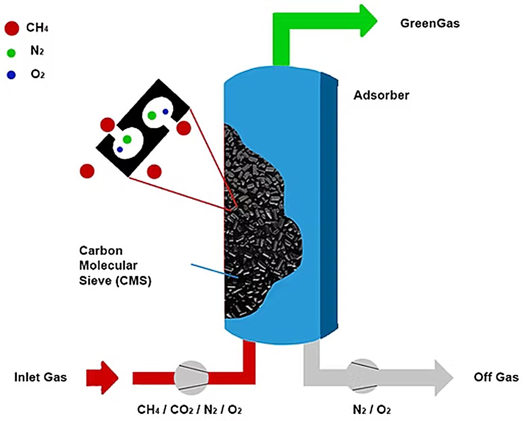
Generic PSA Technology
Owner
/ Undefined Technology Provider
Brand

Description

Technology Overview

Pressure Swing Adsorption (PSA) is a gas separation technique that separates specific gas species from a mixture under pressure according to their molecular characteristics and affinity for selective adsorbent materials. The technology operates at near-ambient temperature, fundamentally differing from cryogenic distillation methods commonly used for gas separation.​

Operating Principle

PSA exploits the property that certain gas molecules preferentially adsorb onto specialized solid adsorbent materials at high pressure and desorb when pressure is reduced. The process relies on varying pressure to achieve separation—the "pressure swing" refers to alternating high and low pressures applied to enable adsorption and desorption cycles.​

Adsorbent Materials

PSA systems employ selective adsorbent materials including zeolites (molecular sieves), activated carbon, and carbon molecular sieves as trapping media. The selection of adsorbent depends on the specific gases being separated, as each material exhibits different molecular affinity, pore size, and surface characteristics. Under high pressure, target gas molecules bind to the adsorbent surface while non-adsorbing gases pass through the bed as product.​

Figure 1 — PSA selective gas molecules adsorption principle [1]

Process Cycle

A complete PSA cycle consists of four fundamental stages:​

  • Adsorption: Compressed feed gas enters a vessel containing adsorbent material at high pressure (typically 5-10 bar). Target components selectively adsorb while product gas exits from the top until the adsorbent reaches saturation capacity​
  • Depressurization/Blowdown: Pressure is reduced in several steps to recover additional pure gas remaining in the bed, then desorbed impurities are vented to the off-gas line​
  • Purge: A small portion of purified product gas flows countercurrently through the bed to remove remaining undesired gases and regenerate the adsorbent for the next cycle​
  • Repressurization: The bed is pressurized back to operating pressure, often using product gas to minimize losses, preparing for the next adsorption cycle​

Figure 2 — Pressure swing adsorption process [2]


Multi-Bed Configuration

PSA systems employ at least two parallel vessels operating 180° out of phase to maintain continuous production. While one bed undergoes adsorption, the other simultaneously experiences desorption and regeneration. Advanced systems incorporate pressure equalization between beds—transferring gas from the pressurized tower to the depressurizing tower to minimize compressed air losses and enhance overall efficiency.​

Process Control

Modern PSA systems are highly automated using Programmable Logic Controllers (PLCs) that manage valve sequencing, maintain appropriate pressure levels, and cycle towers between operating stages. This automation ensures consistent product purity, maximizes system efficiency, and reduces operational errors.​

Industrial Applications

PSA technology is widely deployed for:​

Advantages

PSA offers several advantages over alternative separation technologies:​

  • Operates at near-ambient temperature, avoiding thermal degradation of feed components
  • Minimal energy input required—primarily for compression and pressure cycling
  • Continuous automated operation with high reliability
  • On-site gas production capability, eliminating transportation and storage costs
  • Modular and scalable design for various production capacities

The technology has demonstrated rapid improvement since commercial deployment in the 1970s and remains the preferred method for many industrial gas separation applications.

Step-by-Step Process Description

The following describes a typical 8-tower PSA hydrogen purification system (Fig. 1) operating with 2-tower feed and 3-stage pressure equalization (8-2-3/V configuration):

Figure 3 — Zinder Refinery PSA hydrogen purification unit [9]

Step 1: Adsorption (Feed)

  • Process: Feed gas at high pressure (0.7 MPa) enters the bottom of Adsorber C-101A through open program control valve KV-1001A. As gas flows upward through the adsorbent bed, impurities (CO, CO₂, CH₄, N₂, H₂O) selectively adsorb onto the molecular sieve surface while hydrogen passes through and exits from the top as purified product.​
  • Duration: Approximately 160 seconds​
  • Equipment in operation: Feed gas compressor, adsorber C-101A, inlet valve KV-1001A, outlet valve to product buffer, pressure control valve PV-1003​
  • Key parameter: Adsorption pressure maintained at 0.7 MPa by regulating valve PV-1003

Step 2: First-Stage Pressure Equalization Down (E1D)

  • Process: When Adsorber C-101A approaches saturation, program control valves KV-1002A and corresponding valve on a depressurizing tower open. Gas from the pressurized tower flows to the lower-pressure tower, equalizing pressures between the two vessels and recovering energy.​
  • Duration: ~15 seconds​
  • Equipment in operation: Equalization connecting valves between towers​
  • Key parameter: Pressure reduces from 0.7 MPa to intermediate pressure (e.g., 0.55 MPa)

Step 3: Second-Stage Pressure Equalization Down (E2D)

  • Process: Similar to first equalization, but connecting to a different tower at lower pressure. Gas continues flowing from C-101A to further reduce pressure while transferring gas to another adsorber preparing for adsorption.​
  • Duration: ~15 seconds​
  • Key parameter: Pressure reduces to second intermediate level (e.g., 0.40 MPa)

Step 4: Third-Stage Pressure Equalization Down (E3D)

  • Process: Final pressure equalization connects C-101A to a third tower at even lower pressure. This three-stage equalization maximizes energy recovery and hydrogen recovery efficiency.​
  • Duration: ~15 seconds​
  • Key parameter: Pressure reduces to third intermediate level (e.g., 0.25 MPa)​

Step 5: Countercurrent Blowdown/Depressurization I (BD1/D1)

  • Process: Program control valves KV-1003A and KV-1008A open. Gas flows out from the bottom of C-101A (reverse direction from adsorption) into the desorption gas buffer tank D-104. This countercurrent depressurization begins desorbing impurities from the adsorbent.​
  • Duration: ~25 seconds​
  • Equipment in operation: Bottom outlet valves, desorption gas buffer tank D-104​
  • Key parameter: Pressure reduces from 0.25 MPa to approximately 0.06 MPa

Step 6: Countercurrent Blowdown/Depressurization II (BD2/D2)

  • Process: Regulating valve HV-1003 opens, connecting C-101A bottom outlet to vacuum buffer tank D-105. Continued countercurrent flow further desorbs impurities as pressure approaches vacuum conditions.​
  • Duration: ~25 seconds​
  • Equipment in operation: Vacuum system, vacuum buffer tank D-105, regulating valve HV-1003​
  • Key parameter: Pressure reduces from 0.06 MPa to approximately 0.02 MPa

Step 7: Purge (P)

  • Process: A portion of high-purity product hydrogen from another adsorber flows downward (countercurrent) through C-101A from top to bottom. This purge gas sweeps remaining impurities from the adsorbent bed, completing regeneration. Purge gas exits from the bottom into the tail gas system.​
  • Duration: ~30 seconds​
  • Equipment in operation: Product buffer tank, purge flow control valve, tail gas collection system​
  • Key parameter: Purge flow rate controlled by regulating valve; tower remains at low pressure (~0.02 MPa)

Step 8: First-Stage Pressure Equalization Up (E1U)

  • Process: C-101A receives gas from another tower undergoing first-stage depressurization. Pressure in C-101A begins increasing as it receives transferred gas, recovering energy from the depressurizing tower.​
  • Duration: ~15 seconds​
  • Key parameter: Pressure increases from 0.02 MPa to first intermediate level (e.g., 0.25 MPa)​

Step 9: Second-Stage Pressure Equalization Up (E2U)

  • Process: C-101A receives gas from a different tower at higher pressure undergoing second-stage depressurization. Pressure continues rising toward adsorption pressure.​
  • Duration: ~15 seconds​
  • Key parameter: Pressure increases to second intermediate level (e.g., 0.40 MPa)​

Step 10: Third-Stage Pressure Equalization Up (E3U)

  • Process: C-101A receives gas from a third tower at even higher pressure. This completes the three-stage pressure equalization sequence.​
  • Duration: ~15 seconds​
  • Key parameter: Pressure increases to third intermediate level (e.g., 0.55 MPa)​

Step 11: Final Repressurization (FR)

  • Process: Program control valve KV-1005A and regulating valve HV-1001 open, allowing high-purity product gas to flow from the product buffer tank into the top of C-101A. Pressure rapidly increases to adsorption pressure, preparing the tower to return to Step 1.​
  • Duration: ~40 seconds​
  • Equipment in operation: Product buffer tank, repressurization valve HV-1001, inlet valve KV-1005A​
  • Key parameter: Pressure increases from 0.55 MPa to 0.7 MPa; valve opening controlled by PID to maintain smooth pressurization rate

References

  1. Pearson C., APEX Gas Generators. Pressure Swing Adsorption (PSA) Technology – How It Works (May 31, 2025)
  2. VITO (accessed: Jan 17, 2026). Pressure Swing Adsorption. EMIS MAP-IT CCU Technologies Database
  3. BYJU'S. What is Pressure Swing Adsorption (PSA)? (accessed: Jan 18, 2026) 
  4. Wikipedia. Pressure swing adsorption (accessed: Jan 18, 2026) 
  5. Sustainability Directory. Pressure Swing Adsorption (Nov 26, 2025)
  6. absstem. The Working Principle of Pressure Swing Adsorption (PSA) (Nov 13, 2024)
  7. slideshare. Pressure swing adsorption (n.d.)
  8. Department of Energy (DOE), National Energy Technology Laboratory (NETL). Bench-Scale Development and Testing of Rapid PSA for CO2 Capture (May 22, 2012)
  9. Zinder Refinery Co., Ltd.. Operation Instruction of PSA Unit (Oct 2010)
  10. Feda Nitrogen Inc.. Pressure Swing Adsorption: A Gas Separation & Purification Process (Sep 6, 2018)
  11. ScienceDirect (Dec 2025). Optimization and Comparison of Multi-Beds PSA Systems. DOI: 10.1016/j.ccst.2025.100035X

Insight Articles
Your insights will be shown here

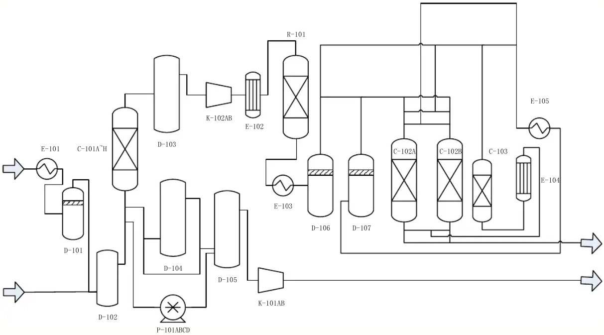
Schematic diagram of a six-bed PSA process (from description ref. nr. 10)
Title Date
Content provided by
Transaction Name Date
Modified by UserPic   Kokel, Nicolas 1/18/2026 4:41 PM
Added by UserPic   Kokel, Nicolas 1/18/2026 9:48 AM