Delayed coking is a semi-batch cyclic thermal cracking process that upgrades residual oils — vacuum residue from the vacuum distillation unit, atmospheric residue, solvent deasphalting pitch, FCC decant (slurry) oil, and unconverted bottoms from ebullated-bed hydrocracking — into lighter products (fuel gas, LPG, coker naphtha, light and heavy coker gas oils) plus a solid carbon product, petroleum coke[2][3] It is the workhorse of the Petroleum Coking technology type: more than 90% of world petroleum coke is produced in delayed cokers, and delayed coking is the most widely applied bottom-of-the-barrel carbon-rejection process, with an installed base of roughly one quarter of the world's ~700 refineries.[1][2] Licensed generic designs are offered today by Wood (SYDEC), Chevron Lummus Global (a Chevron/Lummus Technology joint venture), and Bechtel (ThruPlus, acquired from ConocoPhillips in 2011), alongside extensive in-house design capability at Chinese state refiners (e.g. Sinopec's engineering arms).[4][5][6]
The name "delayed" reflects the defining design principle: the residuum feed is superheated in a fired furnace to about 485–505 °C under short residence time (aided by velocity steam), so that coking in the furnace tubes is "delayed" until the effluent reaches large downstream coke drums, where lengthy residence time at high temperature completes the cracking and polycondensation reactions.[1][2][7] The heart of the unit is the furnace; the product-defining feature is the pair (or pairs) of coke drums that are switched on and off line on a cyclic schedule.[1][2][7]
Process history
Petroleum coke was first made incidentally in the 1860s Pennsylvania pioneer refineries, whose iron stills over-heated and coked the oil near the bottom.[7] From 1912 to 1935 the Burton process (Standard Oil, Whiting, Indiana) thermally cracked gas oil to gasoline with coproduct coke, and the vertical coke drum originates in this thermal-cracking era.[7] The first purpose-built delayed coker was constructed by Standard Oil of Indiana at Whiting in 1929; manual decoking was arduous, and hydraulic decoking with high-pressure water — developed in the late 1930s by Shell at Wood River, Illinois — turned the two-drum arrangement into a genuinely semi-continuous process.[7] Growth was modest before 1955, then surged (about 6%/yr between 1955–1975 and 11%/yr during 1965–1970) in step with fluid catalytic cracking and the decline of pure thermal cracking; today some 55 of ~140 US refineries and roughly 20–25% of the world's refineries operate delayed cokers.[2][7]
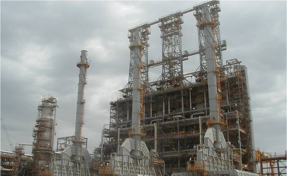
Figure 1 — 6-Drum Delayed Coking Unit | Source: coking.com
Process summary and chemistry
Delayed coking is a purely thermal (non-catalytic) carbon-rejection process. Free-radical cracking of C–C bonds at furnace-outlet temperatures of roughly 485–505 °C generates lighter hydrocarbons that vaporise, while higher-molecular-weight radicals rapidly polycondense in the coke drum at about 430–490 °C into solid green coke; some secondary cracking of vapours continues in the drum void space and transfer line, normally limited by quench-oil injection into the overhead vapour line.[1][2][8] Essentially all feed metals and most sulfur, nitrogen and asphaltenes concentrate in the coke fraction, which acts as a contaminant "sink"; cracking begins in the furnace tubes, continues in the transfer line, and finishes in the coke drum.[1][2][8]
Three operating variables dominate yield and coke quality: furnace-outlet temperature, coke-drum pressure, and recycle ratio.[2][3][8] Higher temperature raises liquid yield and coke hardness (but risks heater fouling and harder cutting); higher pressure and higher recycle ratio increase coke make and gas yield at the expense of distillate; the recycle ratio spans roughly 1.03–1.30 (distillate-maximising units at the low end, premium-coke units higher).[2][8] Fuel-mode units run low pressure (~1 bar drum), low recycle (5–10%), and short cycles; coke-mode (needle/anode) units run higher pressure, higher recycle and longer cycles.[2][3]
Step-by-step process description (generic arrangement)
The following describes the generic unit shared by current licensor designs (furnace, paired coke drums, main fractionator with wash section, wet-gas compression and gas recovery, closed blowdown, hydraulic decoking and coke handling). Values are typical ranges from the cited sources, not design guarantees.
Figure 2 — Delayed Coker Unit Functional Process Flow [9]
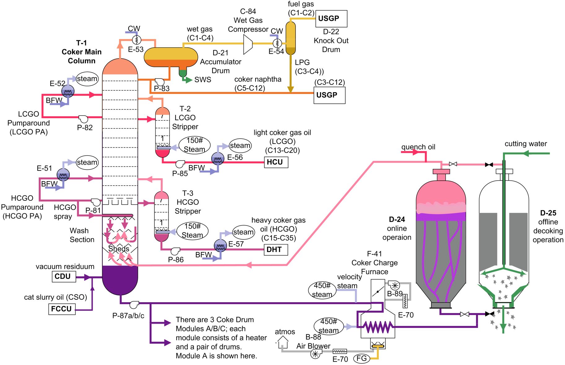
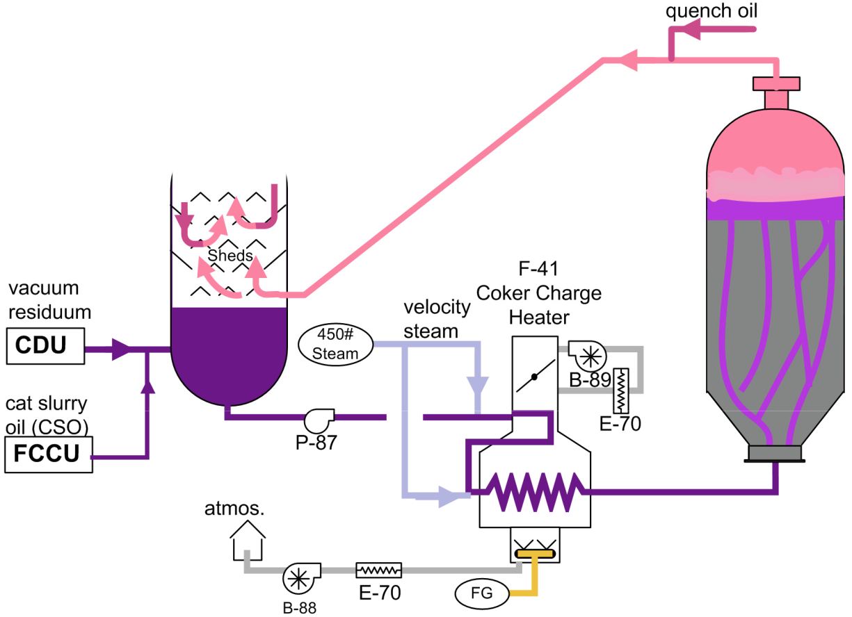
- Feed preheat and fractionator bottoms. Residual oil (typically >600 °F vacuum residuum, sometimes blended with FCC slurry oil) is charged to the bottom of the main fractionator, where it is preheated by direct contact with hot drum overhead vapours; condensed heavy vapours form the natural recycle that is combined with fresh feed at the column bottom.[1][4][9]
- Coker charge heater. The combined feed is pumped through the coker furnace, which raises the coil-outlet temperature to roughly 485–505 °C (about 900 °F+). Velocity steam is injected at the heater inlet and crossover to raise velocity, cut residence time and suppress tube coking; double-fired heater designs give more uniform flux and longer run length, with online spalling or pigging for decoke while the unit remains in service.[1][2][4][9][10]
- Coke drum filling. The superheated two-phase effluent enters the bottom of one of a matched pair of coke drums. Rising through channels in the existing coke bed, the oil accumulates under a foam layer; over an on-stream filling period of typically 16–18 h (drums up to ~1000 m³, roughly 5–9 m diameter and 20–45 m tall; modern units up to 8 drums in 3–4 drum pairs), primary cracking in the liquid phase generates vapour products and lays down solid coke, while secondary cracking is tempered by quench oil in the overhead line.[1][2][9][11] Foam height is controlled (anti-foam injection near cycle end) to protect the vapour line.[2]
- Switching and the decoking cycle. When the drum fills, feed is switched to its sister drum. The full drum is steam-stripped (first to the fractionator, then to the closed blowdown system), water-quenched, drained, unheaded, hydraulically decoked with high-pressure water (drilling a pilot hole, then cutting; water jets up to ~340 bar), re-headed, pressure-tested, air-freed and vapour-heated before returning on line. A full cycle is commonly 16–18 h (older designs 24 h); EPA rules require depressuring to ≤2 psig (or ≤220 °F top temperature) via the closed blowdown system before venting, draining or deheading.[1][2][4][11][12][13]
Figure 3 — Delayed Coker Online Drum Module Operation [9]
- Fractionation and product recovery. Drum overhead vapours enter the main fractionator wash section, where counter-flowing heavy coker gas oil spray desuperheats the vapour, condenses the >~700 °F fraction (which recycles to the drums) and washes out coke fines. Fractionator products are unstabilised coker naphtha, light and heavy coker gas oils (via side strippers), and wet gas; overhead goes through the wet-gas compressor and condensers to a gas-recovery (saturated-gas) plant separating fuel gas, LPG (C3/C4) and naphtha.[1][4][9][11]
- Coke handling and water recovery. Cut coke drops into a pit, pad or sluiceway; dewatering options include direct railcar loading, pit/pad with crane recovery, and fully enclosed hydrobin or closed-coke-slurry systems (crusher → slurry pump → dewatering bins, water recycled via hydrocyclone/clarifier). Water from cutting and quench is clarified and reused; cutting water and fines recovery are integral to modern designs.[4][14][15]
Process performance
Typical product yields (wt% on vacuum-residue feed, fuel mode) are approximately:
- Gas + LPG + H2S ~9–13%
- Total naphtha ~10–21% (cut 21–140 °C)
- Total gasoil ~33–48%
- Green coke ~18–31%
Figure 4 — Coker Main Column and Product Fractionation Curves [9]
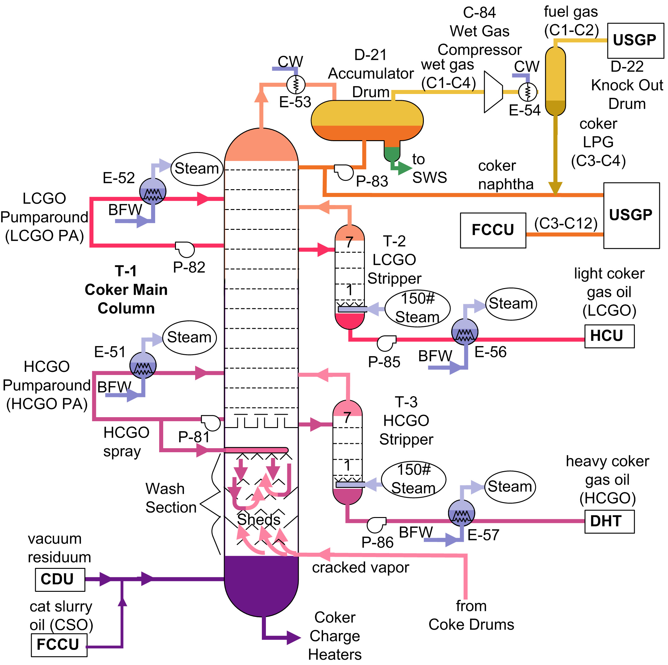
Coke yield tracks roughly 1.2–1.6 × the feed Conradson carbon residue; a common operating conversion figure is ~65 wt% of feed to gas+liquids with ~35 wt% coke.[2][3][8][9][11] Yield structure is tuned by temperature, pressure and recycle ratio; heat-integrated designs maximise air cooling and feed preheat.
Liquid products are olefinic and require hydrotreating: coker naphtha is saturated before reforming/blending, coker gasoils to hydrotreaters, FCC or hydrocrackers, and wet gas to the unsaturated gas plant for olefin recovery and treating.[3][9]
Coke morphology is feed- and condition-dependent: shot coke (spherical, from asphaltenic/heavy feeds; avalanche hazard on unheading), sponge coke (friable, most common; calcines to anode grade when low in sulfur/metals) and needle coke (anisotropic premium product from aromatic, low-contaminant feeds such as FCC slurry oil; requires high pressure, high recycle and long cycles, and commands the highest value — increasingly targeted for synthetic graphite/battery applications).[2][8][9][15][16]
Economic performance
Delayed coking is mechanically one of the simplest and cheapest full-conversion residue-upgrading units in a refinery — essentially a furnace, paired coke drums, fractionator and gas-recovery/blowdown — and this low capital intensity, together with tolerance of the dirtiest feeds, is the main reason it dominates the carbon-rejection market.[2][3][17]
Typical licensed unit sizes have ranged from ~15,000 to 50,000 bpd with the trend upward (single-train designs to ~124,000 bpd first phase / ~180,000 bpd ultimate have been awarded).[4]
No published same-basis CAPEX/OPEX comparison covering current licensor designs was located; licensor material provides only qualitative economics (revamps delivering 20–30% capacity increases, two-to-three-drum conversions raising capacity by ~33.8% at a central Indian refinery in 2019).[18]
Coke is a saleable by-product (fuel grade at the low end; calcined anode and needle coke at progressively higher value), and the PetroPower concept (delayed coker + circulating fluidized-bed combustion of petcoke for power/steam) is an established valorisation route where the solid-fuel market exists.[3][19]
Environmental performance
Historic open-pit decoking and drum venting emitted coke dust, VOCs, H2S and other fugitive emissions, and exposed operators to hot-water eruption and coke-avalanche hazards on drum platforms.[15][20] US EPA rules for delayed coking units (40 CFR 63.657, amended November 2018) require depressurising each coke drum to a closed blowdown system to ≤2 psig (or ≤220 °F/218 °F top temperature, per monitoring provisions) before venting, draining or deheading, with continuous pressure/temperature monitoring — driving ejector or water-ring-compressor additions to blowdown systems and enclosed handling.[13][18] Modern designs feature fully enclosed automatic top/bottom unheading, closed (enclosed) blowdown, clean/enclosed coke handling (hydrobin or closed slurry systems eliminating open pits and coke dust), closed cutting-water circuits, API sludge and slops co-processing, ultra-low-NOx burners, and heat integration; licensor materials report heater run lengths of five years or more between turnarounds with online spalling.[4][14][15][18][20] Flexicoking-type concerns do not apply, but incinerating high-sulfur fuel-grade coke re-releases the sulfur the process had stabilised in the carbon matrix — a central sustainability debate for the technology.[8]
Proprietary technologies and licensors
- Wood (legacy Foster Wheeler / Amec Foster Wheeler) — SYDEC Selective Yield Delayed Coking; proprietary TerraceWall sloped-wall double-fired heaters; 65+ years of coker design experience, 150+ TerraceWall heaters and 70+ licensed units reported; SYDEC Volt (fuel-coker repurposing to needle coke) and SYDEC Circular (plastic-waste co-processing) variants.[6][10][21]
- Chevron Lummus Global (Chevron U.S.A. / Lummus Technology JV) — proprietary delayed coking design based on 60+ unit designs and commercial installations; vertical-plate coke-drum technology, fully enclosed automatic flange unheading, helical-baffle exchangers, low-pressure/ultra-low-recycle design, proprietary coke pit/pad and structure design, API sludge disposal process, predictive yield tools and dynamic OTS simulation.[5]
- Bechtel (Bechtel Hydrocarbon Technology Solutions) — ThruPlus coking technology (acquired from ConocoPhillips in 2011); 50+ years of delayed coking project experience (e.g. INA Rijeka license, 2014; Egyptian refinery selection).[22][23]
- China (Sinopec, PetroChina and independent refiners) — large domestically-designed installed base; Sinopec's Closed Coke Handling System (S-CCHS, introduced via PTQ webinar, 2023) packages pollution-free coke removal/conveying/storage with remote intelligent operation for retrofit across Chinese DCUs.[15][24]
- Specialised equipment suppliers (not licensors of the process itself): DeltaValve/CIRCOR (slide-valve unheading, CenterFeed injection), Flowserve and competitors (hydraulic decoking), DeltaValve-style enclosed systems — these configure within the licensor packages above.[25]
Global capacity and growth trend
World coking capacity stands at about 9.7 million bbl/d (OPEC WOO 2025 base, January 2026), concentrated in the US & Canada (~2.8 mb/d), China (~2.4), India (~1.1), Latin America (~1.0), Europe (~0.8), Russia/Eurasia (~0.6), Other Asia-Pacific (~0.4) and the Middle East (~0.5); essentially all of it is delayed coking, with only a handful of fluid/flexicokers.[26] The US operates ~2.5–2.7 mb/d of coker capacity with fresh-feed inputs above 5.0 mb/d (EIA Refinery Capacity 2026), the largest single-country installed base.[11] OPEC projects only ~0.6 mb/d of new coking/visbreaking capacity from existing projects 2026–2030 and ~3.0 mb/d total coking/visbreaking additions to 2050 — modest growth concentrated in Asia and the Middle East as fuel-oil demand declines and IMO-type sulfur rules push more residue into conversion; growth increasingly favours revamps (capacity, needle-coke conversion, energy efficiency/decarbonisation) over grassroots units in mature markets.[18][26]
References
- Britannica — A.L. Waddams, Petroleum refining: Visbreaking, thermal cracking, and coking
- IntechOpen — Jafar Ramezanzadeh & Hossein Moradi, Coking, Topics on Oil and Gas (DOI: 10.5772/intechopen.106190; published: Dec 20, 2023)
- Wagner da Silva M. (Petrobras) & Clark J. (Coke Consulting Company) — Delayed coking as a sustainable refinery solution, PTQ Q2 2021.
- Malik R. & Hamilton G.L., ABB Lummus Global — Delayed coker design and project execution, PTQ Q4 2002.
- Chevron Lummus Global — Delayed Coking technology sheet (PDF created: Jan 20, 2021)
- Wood — Delayed coking technology for zero-fuel oil production (SYDEC™) (accessed: Nov 21, 2026); Wood — Technology licensor for SYDEC™ delayed coking brochure
- Ellis P.J. & Paul C.A., Great Lakes Carbon Corporation — Tutorial: Delayed Coking Fundamentals, AIChE 1998 Spring National Meeting, New Orleans (Mar 9, 1998).
- Ramesh K., Indian Oil Corporation — Estimating delayed coker yields, PTQ Q1 2020
- Visual Performance Solutions / Averill W., Full Conversion Refinery Operations Handbook (ROHB) — ROHB-16 Delayed Coking Unit (DCKU), Chapter 4 excerpt, Rev 1 (Mar 2024)
- Cabello J.R., Amec Foster Wheeler — Delayed Coking Operational Optimization, RefComm Rio de Janeiro (Sep 29–Oct 3, 2014)
- U.S. Energy Information Administration — Refinery Capacity Report 2026 (Table 8: capacity and fresh feed input to selected downstream units; published: Jun 2026).
- Wikipedia — Delayed coker (latest update: Feb 11, 2026).
- U.S. EPA — 40 CFR 63.657: Delayed coking unit decoking operation standards (as amended Nov 26, 2018; accessed: Nov 21, 2026).
- Chevron Lummus Global — CLG Delayed Coker — Coke Handling Systems diagram
- Sinopec (LPEC) — Introduction to the Sinopec Closed Coke Handling System (S-CCHS) webinar (PDF created: Dec 18, 2023)
- Manral V. et al., Chevron Lummus Global — The attractive market opportunity for synthetic graphite, Hydrocarbon Processing (Aug 2024 / Jan 2025; cited in ref. 19)
- McKinsey Energy Insights — Coker, Refinery Reference Desk (accessed: Nov 21, 2026
- Manral V. & Magdoza K., Chevron Lummus Global — Unlock value through coker revamps, Hydrocarbon Processing (PDF created: May 25, 2026)
- Giglio R., Sumitomo SHI FW — The power option, PTQ Q1 2019
- IOCL Barauni Refinery — Presentation on Delayed Coker
- Wood — Foster Wheeler Delayed Cokers project list (A Barrel Full)
- Bechtel — Bechtel's ThruPlus® Coking Technology Selected for Croatian Refinery (Feb 28, 2014)
- Bechtel — Bechtel's ThruPlus® Delayed Coking Technology Selected for Egyptian Refinery (press release; accessed: Nov 21, 2026)
- DigitalRefining — S-CCHS company/product literature (accessed: Nov 21, 2026)
- CIRCOR DeltaValve — CenterFeed™ injection and slide-valve unheading systems (accessed: Nov 21, 2026)
- OPEC — World Oil Outlook 2025, Chapter 5: Refining outlook (Tables 5.1, 5.6, 5.7; published: 2025)