Technology History and Summary
The TPR™ (Technip Parallel Reformer) was developed by Technip Energies Process Technology — a lineage tracing back to KTI (Kinetics Technologies International), founded in 1963 as SELAS of America (The Netherlands). KTI introduced heat exchanger reformer (HER) concepts in the 1990s as part of its "Advanced Reforming Technology" (ART) program to reduce capital and operating costs of hydrogen and syngas plants. Following the integration of KTI into the Technip group and eventually Technip Energies (spun off from TechnipFMC in 2021), the technology was refined and trademarked as the TPR — a convective–regenerative heat exchange reformer that optimizes high-grade heat recycling while increasing reforming capacity without additional fuel firing.
The TPR is essentially a gas-heated reformer (GHR) working in parallel with a conventional fired Steam Methane Reformer (SMR). Unlike a conventional SMR, which relies on radiant heat transfer from combustion flue gas, the TPR derives its reaction heat from the hot process gas (reformed syngas effluent) exiting the fired SMR. Asof Feb 2026, Technip Energies has designed and supplied 11 operating TPR references, with standalone hydrogen generation capacities ranging from 3 to 25 kNm³/h per unit.
 |
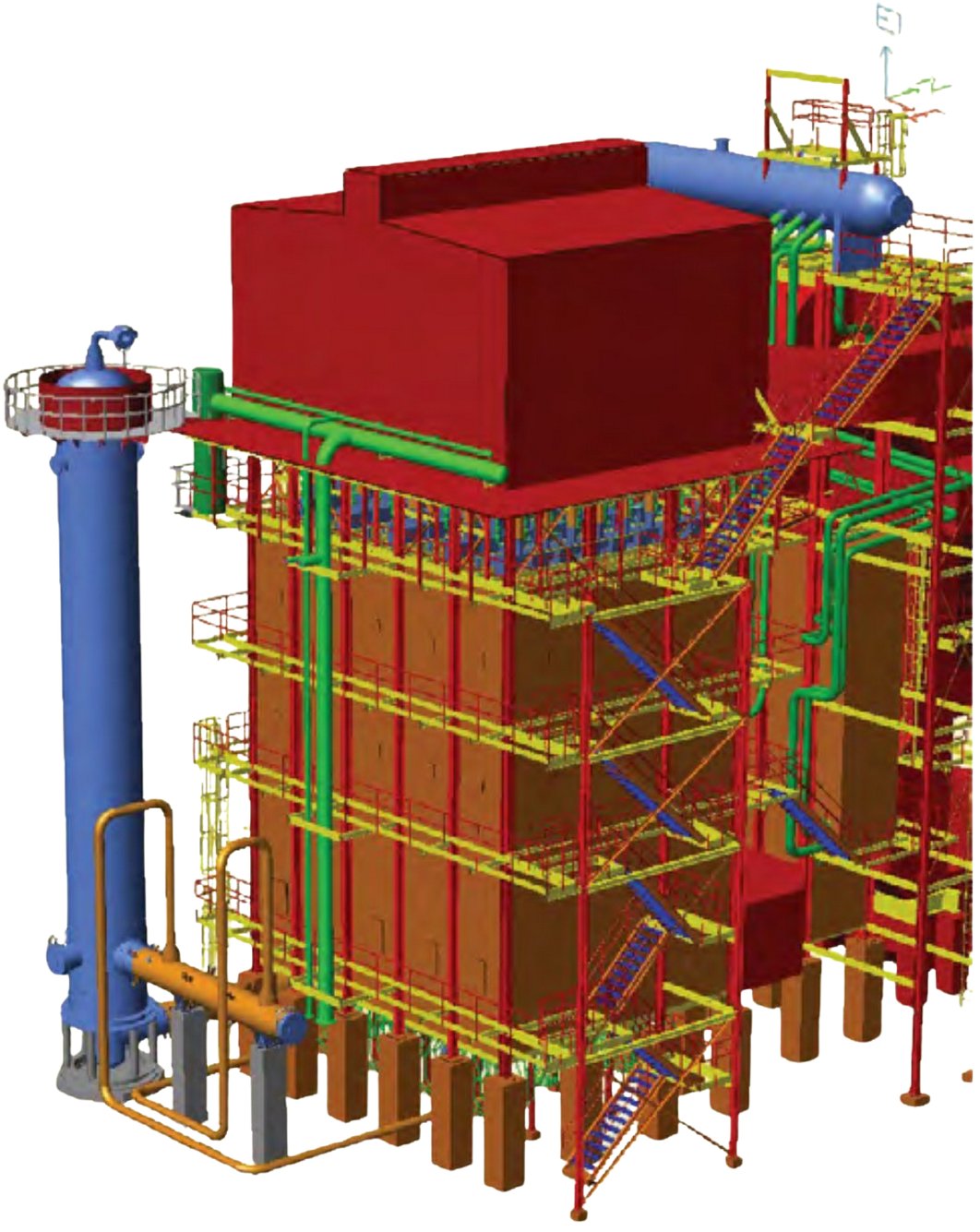 |
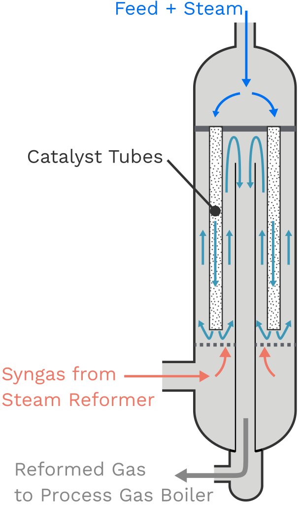
Figure 1 — Left: The TPR™ is a reactor in which hydrogen is produced
by steam reforming; Right: TPR adjacent to the SMR |
The HPCL Visakh grassroot installation (2018–2021) marked the first-ever grassroots installation of the TPR™ technology — all prior references had been capacity revamps of existing plants. This milestone demonstrated the technology's viability not only for debottlenecking but also for new-plant design.
Process Description
Feed Preparation and Pre-Treatment
Before entering the TPR, the hydrocarbon feedstock (natural gas, naphtha, or LPG) undergoes desulfurization and, optionally, pre-reforming. At the HPCL Visakh unit, an integrated pre-desulphurization section reduces the sulfur content of naphtha feedstock before it is sent as sweet naphtha to the main HGU. When a pre-reformer is present (as is the case in most Indian references), the feed entering the TPR is pre-reformed effluent rather than raw natural gas, which contributes to higher conversion efficiency in the tubes.
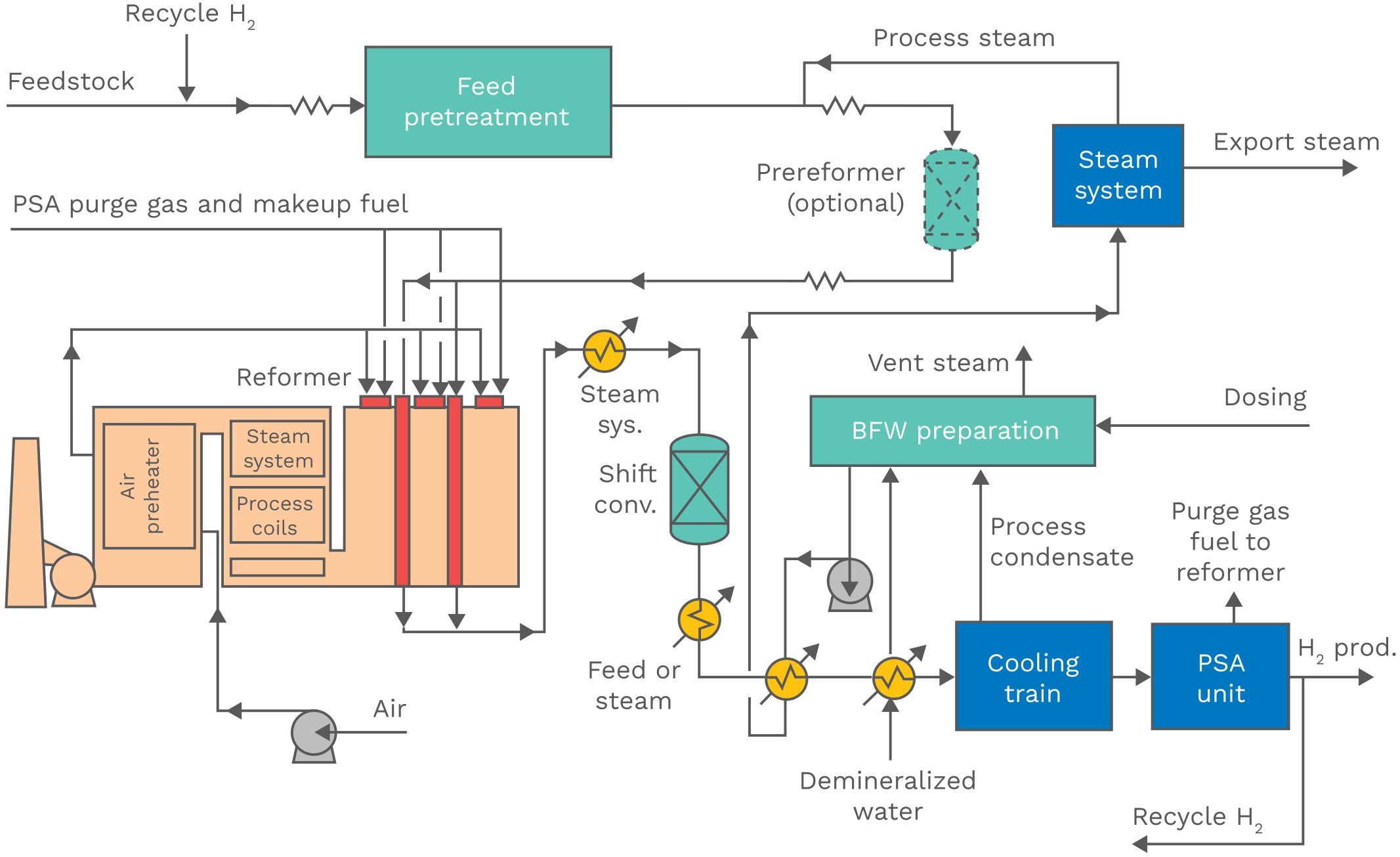
Figure 2 — Technip Energies Hydrogen Generation Unit (HGU) - TPR not shown in this diagram
TPR Reactor — Internal Flow Configuration ("2-in, 1-out")
The TPR vessel is a vertically oriented, refractory-lined tubular reactor with a single tube sheet at the top. The internal flow configuration is proprietary and described as a "2-in, 1-out" arrangement:
- Tube-side (reforming): Pre-heated feed gas (natural gas with steam, or pre-reformer effluent) enters from the top of the TPR and flows downward through catalyst-filled tubes. The endothermic reforming reactions convert the feed to an equilibrium mixture of H₂, CO, CO₂, CH₄, and H₂O — identical to the reactions occurring in the main fired SMR.
- Gas mixing at the bottom: At the bottom of the tube bundle, the process gas exiting the tubes is mixed with the incoming hot SMR effluent, which enters the shell side from the bottom of the vessel.
- Shell-side (heat supply): The hot gas mixture flows upward through the refractory-lined shell, transferring the heat of reaction to the tube-side catalyst bed. This counter-current arrangement maximizes the temperature driving force along the tube length.
- Central collector pipe: A proprietary central collector pipe in the middle of the reactor directs the mixed reformed gas downward and back to the bottom outlet of the TPR, avoiding an external hot transfer line to the downstream process gas boiler.
- Process Gas Boiler: The combined effluent (TPR tube-side + SMR effluent) exits at the bottom of the TPR and is directed to the Process Gas Boiler (PGB), where high-pressure steam is generated by cooling the process gas to the temperature required for downstream water-gas shift conversion.
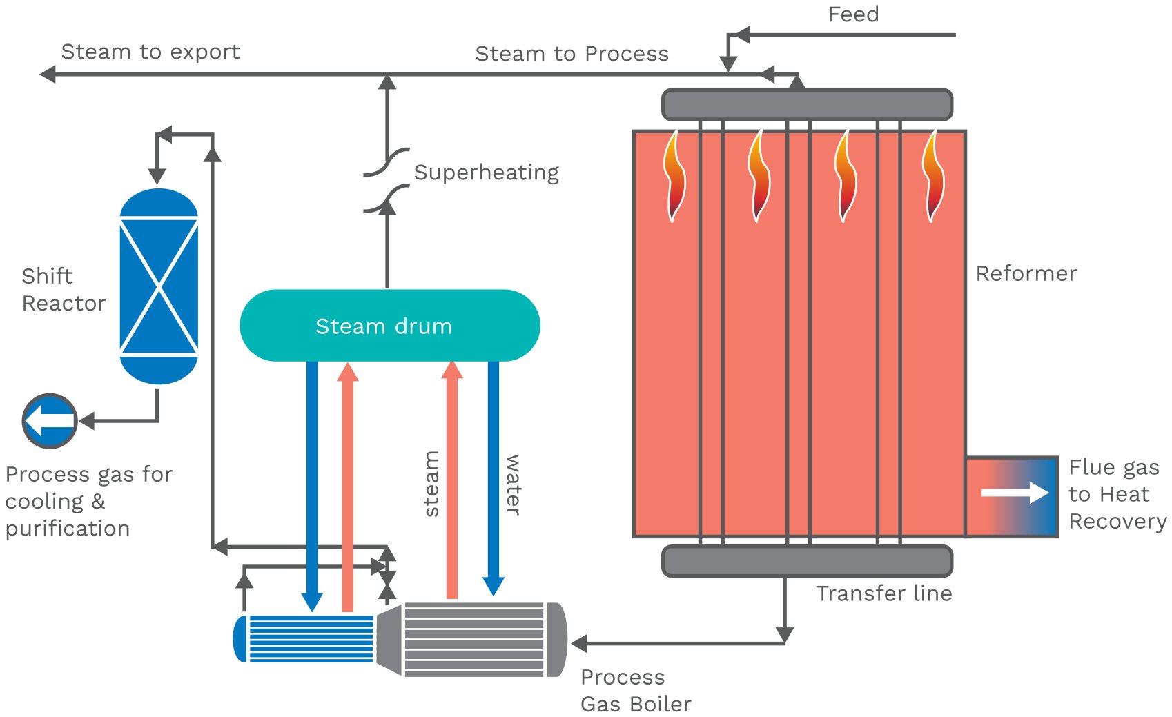
Figure 3 — Role of the dual chamber PGB in a hydrogen plant
Shift Conversion and H₂ Purification
Downstream of the TPR and PGB, the process follows the conventional SMR flowsheet:
- Water-Gas Shift (WGS) conversion: CO in the reformed gas reacts with steam to produce additional H₂ and CO₂.
- PSA purification: A Pressure Swing Adsorption (PSA) unit delivers high-purity hydrogen product (up to 1 ppm CO) at near-inlet pressures. PSA purge gas is recycled as fuel to the SMR furnace.
Operating Parameters and Conditions
The TPR operates under conditions comparable to the associated SMR. Key parameters reported in Technip Energies documentation include:
| Parameter |
Typical Range / Value |
| Feedstock |
Natural gas, naphtha, LPG,
or pre-reformer effluent |
| Steam-to-carbon ratio (S/C) |
Matched to SMR;
typically 2.5–3.5 mol/mol |
| SMR outlet temperature (heat source) |
800–950 °C |
| TPR tube-side outlet temperature |
Approaches SMR
outlet equilibrium |
| Operating pressure |
Moderate (matched to existing plant;
typically 20–35 barg) |
| Heat supply mechanism |
Convective (hot process gas),
not radiative/combustion |
| Add-on hydrogen capacity |
3–30 kNm³/h per unit;
up to 30% of base plant capacity |
Because the TPR is not a fired unit, it does not have its own burners, stack, or air preheater — it solely relies on the thermal energy of the hot SMR effluent. The tube bundle design, tube sheet metallurgy, and material selection are critical engineering parameters given the high-temperature, high-pressure syngas environment.
Equipment List
A full-scale Hydrogen Generation Unit (HGU) based on Technip Energies' steam reforming technology with an integrated TPR© comprises the following major equipment items, grouped by process section:
Feed Preparation and Desulfurization
- Feed gas compressor — boosts feed pressure (natural gas, naphtha, or LPG) to plant operating pressure
- Feed preheater — convective coil in the SMR flue gas duct; preheats feed to desulfurization temperature
- Hydrogenation reactor — fixed-bed reactor (Co-Mo or Ni-Mo catalyst) converting organic sulfur compounds to H₂S
- ZnO guard bed vessels — one or two fixed-bed vessels in series (ZnO sorbent) for bulk H₂S removal to <0.1 ppm
- Hydrogen recycle compressor — recycles a slip stream of product H₂ to the hydrogenation reactor to maintain a reducing atmosphere
Pre-Reforming Section (when included)
- Feed/steam mixed preheater — convective coil preheating the desulfurized feed + steam mixture ahead of the pre-reformer
- Adiabatic pre-reformer vessel — fixed-bed reactor (highly active Ni catalyst) converting higher hydrocarbons (C₂+) to CH₄, H₂, CO, and CO₂ at ~400–550 °C; stabilizes feed composition for the main reformer
Steam Generation and Steam System
- Boiler feedwater (BFW) preheater — recovers heat from flue gas or process gas streams
- Steam drum — high-pressure (HP) steam drum maintaining steam/water circulation
- Saturator (optional) — saturates the hydrocarbon feed with steam by direct contact, reducing the need for external steam injection
- Process steam superheater — convective coil in the SMR flue gas duct; superheats HP steam before injection into the feed/steam mix
- Export steam superheater — superheats excess HP steam for export to the site steam network (reduced or eliminated in TPR© configurations)
Fired Steam Methane Reformer (SMR Furnace)
- Reformer furnace (fired heater) — top- or side-fired refractory-lined furnace box with arrays of reformer tubes filled with Ni-based reforming catalyst; operates at 800–950 °C tube outlet temperature and 20–40 barg
- Reformer tubes — high-alloy centrifugally cast tubes (HP-Nb, HP-Micro, or similar metallurgy) containing reforming catalyst
- Burners — top-fired or side-fired Ultra-Low-NOx burners; Technip Energies offers proprietary designs including the Technip Side Wall Burner (TSWB©) and Large Scale Vortex (LSV©) burner
- Flue gas duct (convection section) — downstream of the radiant furnace box; houses multiple heat recovery coils (feed preheat, steam superheat, combustion air preheat, BFW preheat, fuel gas preheat)
- Combustion air blower/fan — forced or induced draft fans for combustion air supply
- Stack — with or without selective catalytic reduction (SCR) unit for DeNOx
- SCR (Selective Catalytic Reduction) unit (optional) — reduces NOx in flue gas using ammonia or urea injection over a vanadium/titania catalyst
TPR Section — Technip Parallel Reformer
- TPR vessel — vertically oriented, refractory-lined pressure vessel with top tube sheet, catalyst-filled reformer tubes, central collector pipe, and integrated shell-side flow path; the HPCL Visakh units measure approximately 2.4 m OD × 23.5 m length, weighing ~150 t each
- TPR catalyst tubes — alloy tubes filled with Ni-based reforming catalyst (same catalyst family as SMR tubes)
- Hot transfer line (SMR outlet to TPR shell) — refractory-lined piping conveying ~850–950 °C SMR effluent to the TPR shell inlet; eliminated in the proprietary "2-in, 1-out" integrated design
Process Gas Cooling and Heat Recovery
- Process Gas Boiler (PGB) — Technip Energies proprietary Dual Chamber Process Gas Boiler; cools combined SMR + TPR effluent from ~850 °C to ~350 °C while generating HP steam; the dual-chamber design accommodates the mixed effluent from both reformers
- Process gas steam drum — associated with the PGB for HP steam generation
- High-temperature shift (HTS) reactor — fixed-bed reactor (Fe-Cr catalyst) converting CO + H₂O → CO₂ + H₂ at ~350–450 °C
- Low-temperature shift (LTS) reactor (optional) — fixed-bed reactor (Cu-Zn-Al catalyst) for further CO conversion at ~200–250 °C, used when maximum H₂ yield is required
- Process gas coolers/condensers (series) — tube-and-shell heat exchangers cooling shifted gas from ~200 °C to ~40 °C ahead of PSA; generate medium- and low-pressure steam or preheat BFW
- Knock-out drum / condensate separator — separates condensed process condensate from the cooled shifted gas
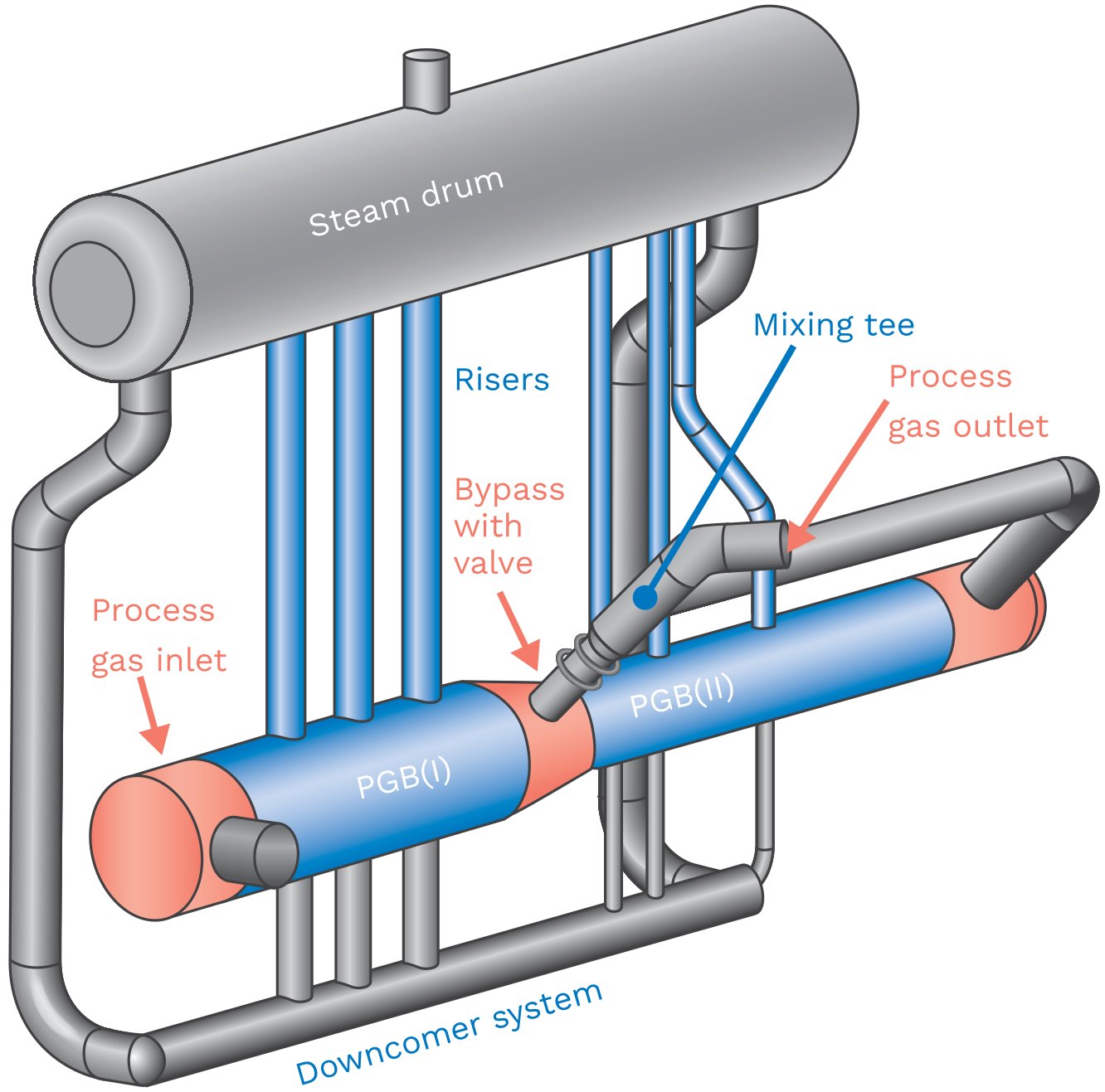
Figure 4 — Dual chamber PGB
Hydrogen Purification — PSA Unit
- PSA adsorber vessels — multiple parallel vessels (typically 8–16) containing layered adsorbent beds (activated alumina, silica gel, activated carbon, zeolite 5A); operate in staggered pressure-swing cycles to deliver high-purity H₂ product (≥99.9 vol%, ≤1 ppm CO)
- PSA feed surge drum — stabilizes feed pressure to the PSA
- PSA product buffer drum — smooths hydrogen product flow
- PSA tail gas (purge gas) drum — collects PSA purge gas for return as fuel to the SMR burners
Hydrogen Recovery Unit (HRU) (when included)
- HRU membrane separator or PSA — recovers hydrogen from refinery off-gas streams
- Condensing steam turbine generator — at HPCL Visakh, the excess HP steam from the HGU drives a condensing turbine to generate power for the HRU, making the plant self-sufficient in utilities
Utilities and Ancillaries
- BFW treatment package — deaerator, chemical dosing, polishing filters
- Condensate stripper — strips dissolved gases (CO₂, NH₃) from process condensate before recycle to BFW system
- Flare system / pressure relief headers — safety relief for process gas streams
- Instrument air and nitrogen systems — for purging, blanketing, and instrument supply
- DCS / Safety Instrumented System (SIS) — plant-wide control and safety logic; Technip Energies offers an Operator Training Simulator (OTS) as an optional add-on
Process Efficiency
Hydrogen Yield and Capacity Increase
The primary efficiency advantage of the TPR is the recovery of high-grade heat from the SMR effluent that would otherwise be downgraded to steam generation in the Process Gas Boiler. By using this heat for additional reforming:
- Up to 30% additional hydrogen can be produced from the same fuel firing in the SMR.
- World-scale hydrogen plants equipped with TPR have reported confirmed capacity increases of 20–30%.
- The overall reforming fuel demand is significantly reduced — up to 20–30% less fuel per unit of additional H₂ — because part of the reforming heat duty is met by process-to-process heat exchange.
Steam Export and Energy Balance
A key efficiency trade-off is steam generation. Since the hot SMR effluent is used to heat the TPR rather than generate steam in the PGB, export steam production is reduced significantly. Technip Energies leverages this feature strategically:
- In applications where steam revenues are unfavorable, the TPR is the preferred solution.
- The design can be optimized for zero export steam, enabling completely self-sufficient plants that require no external steam network connection.
- At the HPCL Visakh HGU, excess HP steam is used by a condensing steam turbine generator to power the Hydrogen Recovery Unit (HRU), making the facility self-sufficient in both steam and power.
CO₂ Footprint
Because no additional fuel is burned in the TPR, the CO₂ footprint per unit of hydrogen produced is lower compared to building an equivalent additional SMR capacity. The HPCL Visakh project specifically cited minimization of CO₂ emissions as a key driver for selecting the TPR configuration.
Specific Energy Consumption
For the broader Technip Energies hydrogen plant platform (SMR + TPR), typical specific energy consumption ranges from 3.0 to 3.5 Gcal/kNm³ of H₂ (330–370 Btu/scf) on a lower heating value (LHV) basis, depending on feedstock and steam export balance.
Economic Aspects
Capital Cost
The TPR offers significant CAPEX advantages relative to alternative capacity expansion routes:
- Lower cost per unit of incremental hydrogen than adding a new SMR or building an entirely new plant.
- Minimum plot area required, as the TPR vessel is compact and placed immediately adjacent to (or integrated with) the existing SMR structure.
- Faster execution: The installation fits within a typical plant turnaround schedule, avoiding the need for extended planned shutdowns.
- No additional furnace, burner train, or flue gas system is required, substantially reducing civil, structural, and refractory engineering scope.
Operating Cost
- No incremental fuel firing means no additional fuel costs for the added reforming duty.
- Reduced or zero steam export may represent an opportunity cost if steam has high commercial value in the site energy balance; conversely, it avoids the cost of external steam networks in standalone plants.
- Lower NOx emissions (no additional burners) reduce flue gas treatment requirements.
- Fewer rotating equipment items (no additional compressors or blowers for combustion air) reduce maintenance burden.
Licensing and Engineering Model
Technip Energies offers the TPR™ under a technology licensing model covering: technology license, basic design engineering package (BEP), and full EPCC (Engineering, Procurement, Construction, and Commissioning) services — as demonstrated in the HPCL Visakh contract awarded in 2018 on an LEPCC basis.
Commercial Experience
As per the February 2026 edition of the TPRTM Flysheet, 11 operating references have been documented, with hydrogen capacities ranging from 3 to 25 kNm³/h per TPR unit. The reference table below summarizes key commercial installations:
| Location |
Start-up Year |
Feedstock |
Pre-reformer |
Add-on Capacity (kNm³/h) |
Capacity Increase (%) |
| Spain |
2003 |
NG/Naphtha |
Yes |
3.4 |
25 |
| Spain |
2009 |
Natural Gas |
Yes |
9 |
26 |
| USA |
2010 |
Natural Gas |
No |
5 |
30 |
| USA |
2011 |
Natural Gas |
No |
9 |
24 |
| France |
2012 |
Natural Gas |
Yes |
21 |
22 |
| India |
2017* |
Naphtha |
Yes |
20.5 |
20 |
| India |
2017* |
Naphtha |
Yes |
7 |
20 |
| India |
2017* |
NG/Naphtha |
Yes |
2.8 |
20 |
| India |
2018 |
LPG/Naphtha |
Yes |
24.7 |
23 |
| India (Visakh) |
2018* / 2021 |
Naphtha |
Yes |
2 × 30** |
24 |
*Year of award; **Grassroot unit
The HPCL Visakh project represents the largest and most complex TPR installation to date. Contracted in 2018 and delivered in 2021, the project comprised two grassroot HGUs each with a design capacity of 113 KTPA (total 226 KTPA hydrogen) plus a 36 KTPA Hydrogen Recovery Unit (HRU), for a combined hydrogen production capacity of 262 KTPA. This was also the world's first grassroot (non-retrofit) application of the TPR, with each unit incorporating a 30 kNm³/h TPR — the largest individual TPR unit in the reference list.
A notable prior large installation is the France reference (2012) with 21 kNm³/h add-on capacity and a reported 22% capacity increase, corresponding to a 97,000 Nm³/h total hydrogen output plant — one of the world's largest single-train hydrogen plants using the TPR.
References
- Technip Energies — Aksam A., & Pitcher M. (Feb 2026). TPR™ Technip Parallel Reformer Flysheet
- Technip Energies — HPCL Visakh Facility Case Study: Boosting Hydrogen Production and Sustainability (Case Study, 2021; PDF updated June 2024)
- Technip Energies — Technology Handbook (Oct 2023), pp. 104–112 [TPR section, p. 112; Hydrogen section, p. 104–111]
- U.S. Department of Energy / OSTI — Giacobbe F., & Loiacono, O. (Dec 31, 1998). KTI's Innovative Reformer Design for Hydrogen and Syngas Plant
- Technip Energies — Khurana V., & Eyries D. (Feb 2023). Hydrogen
- Technip Energies — Aksam A., & Pitcher M. (2025). The dual-chamber process gas boiler