Process History
Absorption of hydrocarbons from gas into a liquid oil is one of the oldest gas-processing technologies:
-
Early 1900s–1920s: First applied in the natural gasoline industry (USA) to recover heavier hydrocarbons (“casinghead gasoline”) from associated gas, replacing earlier compression and condensation methods. Early plants used “absorption oil” (typically a naphtha cut) in bubble-cap tray columns.
-
1930s–1950s: Widespread adoption for natural gasoline and LPG recovery; integration into refinery saturated gas plants to recover C3+ from FCC and coker off-gases. The concept of the “sponge absorber” emerged in refinery FCC units.
-
1960s onward: Cryogenic turboexpander processes progressively displaced lean oil absorption for high ethane recovery (>70–90% C2) in gas processing, because absorption alone achieves only modest ethane recovery at practical oil circulation rates.
-
Today: Lean oil absorption remains the standard technology in refinery gas concentration/recovery units (FCC, delayed coker, hydrocracker off-gas treatment) for C2/C3+ recovery, and for moderate ethane recovery where cryogenics is not economically justified.
Process Summary
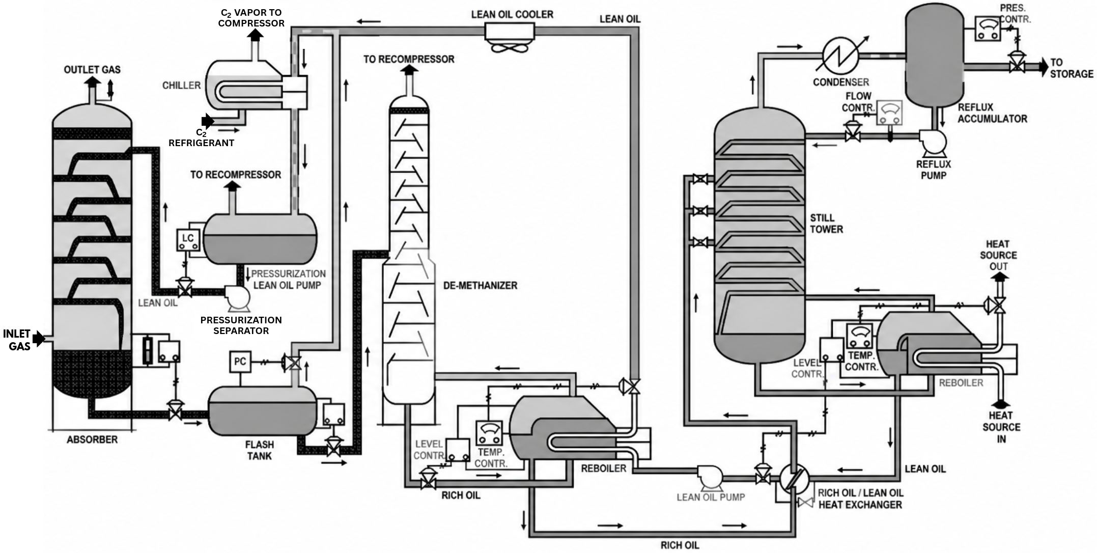
Lean oil absorption is a physical separation process in which a gas stream is contacted counter-currently with a low-volatility hydrocarbon liquid (“lean oil” or “sponge oil” — typically heavy naphtha, kerosene, or light gas oil, MW ~100–200). Heavier gas components (C2+, primarily C3+) dissolve preferentially into the oil. The “rich oil” is then regenerated by distillation (stripper/deethanizer), recovering the absorbed components as products, and the regenerated “lean oil” is recycled.
Main applications:
-
Recovery of LPG (C3/C4) and naphtha from refinery fuel gas (FCC, coker, reformer off-gas)
-
Moderate ethane recovery for petrochemical feedstock
-
NGL recovery from natural gas (legacy/ moderate-recovery plants)
Chemistry / Thermodynamic Basis
-
No chemical reaction occurs — the mechanism is physical solubility governed by vapor-liquid equilibrium.
-
Absorption of component i is described by the equilibrium K-value: Ki = yi / xi, a function of temperature, pressure, and oil properties.
-
The Kremser equation (Kremser, 1930) governs theoretical-stage absorption performance: recovery of a component increases with the absorption factor A = L/(K·V) (liquid/gas ratio relative to K-value).
-
Key principles:
-
Lower temperature → lower K-values → better absorption
-
Higher pressure → better absorption
-
Heavier lean oil (lower volatility) → lower oil loss to overhead gas, but higher circulation needed
-
Absorption is exothermic (heat of solution); intercooling improves recovery.
Step-by-Step Process Description
Typical refinery application (coker/FCC wet gas with ethane recovery):
Step 1 — Gas Compression & Cooling
-
Wet gas compressed in a multi-stage centrifugal/reciprocating wet gas compressor to 10–20 bar(g)
-
Interstage cooling with knockout drums removes condensed liquids
-
Final discharge cooled to 30–40 °C (air/water cooling); refrigerated cooling to ~5–15 °C where higher recovery is needed
Step 2 — H2S Removal (Amine Treating)
Step 3 — Primary Absorber
-
Compressed gas enters the bottom of the absorber (trayed or packed column, typically 20–40 theoretical stages including presaturator sections)
-
Lean sponge oil introduced at the top; typical L/G ratio set so absorption factor A ≈ 1.2–1.4 for the target key component
-
Intercoolers (pump-around circuits) remove heat of absorption
-
Overhead: treated fuel gas (H2, CH4, N2, residual C2) to refinery fuel system or to a secondary sponge absorber
Step 4 — Sponge (Secondary) Absorber (refinery configuration)
Step 5 — Rich Oil Handling / Stripper (Deethanizer)
-
Rich oil preheated by lean/rich exchangers, fed to a stripper or deethanizer column (typically 20–30 trays)
-
Reboiler duty supplied by steam or hot oil; column overhead at conditions yielding C2 product (deethanizer overhead) or C3+ product depending on configuration
-
Typical deethanizer: pressure 15–30 bar, overhead temp ~−10 to 40 °C, reboiler 120–200 °C (values vary strongly with design; confirm against licensor data)
Step 6 — Product Fractionation
Step 7 — Lean Oil Regeneration & Recycle
-
Stripped oil cooled (against rich oil, then air/water), a slipstream purged to control heavies buildup, makeup oil added; recycled to absorber top
Typical Operating Envelope
| Parameter |
Typical Range |
| Absorber pressure |
7–20 bar(g) |
| Absorber temperature |
5–40 °C (refrigerated variants lower) |
| Lean oil molecular weight |
100–200 g/mol |
| Lean oil circulation |
Set by Kremser design; increases
sharply for C2 vs C3 recovery |
Process Performance
Confirmed literature values:
-
Propane recovery: typically 80–95% achievable in conventional lean oil absorption
-
Ethane recovery: typically 20–50% at economic circulation rates; >70% generally requires cryogenics (turboexpander)
-
Butanes+ recovery: >95–99%
-
Lean oil losses: minimized by sponge section; typically small fraction of circulation rate (makeup required)
-
Selectivity: non-selective physical equilibrium — light ends (H2, CH4) largely unabsorbed; residual methane in rich oil stripped in deethanizer
Economic Performance
Publicly available, technology-specific CAPEX/OPEX figures for lean oil absorption are scarce. Established qualitative economics from multiple sources are:
-
CAPEX: Lower than cryogenic turboexpander plants of equivalent capacity (no turboexpander, brazed-aluminum cold box, or deep refrigeration); major cost items are compressors, absorber/stripper columns, and heat exchange network
-
OPEX: Dominated by compression power and reboiler energy for oil regeneration; lean oil makeup; amine treating utilities
-
Economic crossover: For ethane recovery above ~60–70%, cryogenic processes generally show lower total cost of ownership; absorption favored for C3+-only recovery and in refinery gas plants where sponge oil is available in-situ at no incremental cost
Environmental Performance
-
No process emissions from chemistry (physical separation); no catalyst, no chemical reagent consumed except amine in associated treating
-
Emissions sources: compressor drivers (gas turbines/engines → NOx, CO2), fugitive VOC emissions from valves/flanges (managed under LDAR programs), oil purge stream (typically returned to refinery pool)
-
Energy intensity: moderate; heat integration (lean/rich exchange) standard practice
-
Positive environmental role: reduces refinery flaring by recovering valuable hydrocarbons; enables fuel-gas quality control (H2S removal upstream)
Proprietary Technologies, Providers & Licensors
Lean oil absorption is largely a mature, non-proprietary technology; however, licensors offer proprietary optimized gas-plant designs incorporating it:
| Company |
Offering / Notes |
| Honeywell UOP |
Refinery gas recovery/saturation gas plant designs; UOP Sponge Absorber configurations for FCC units |
| Lummus Technology |
Refinery gas recovery units integrated with FCC/coker technology licenses |
| Axens |
Gas treatment and recovery solutions within refinery process licensing |
| Shell |
Saturated gas plant designs for Shell-licensed refineries |
| Wood / Worley / Technip Energies (EPC) |
Design & engineering of custom absorption units |
| Sinopec (SEI/LPEC) |
Proprietary FCC gas recovery designs deployed across Chinese refineries |
| Lukoil / VNIPIneft / Gazprom entities |
Domestic gas plant designs for refineries and NGL recovery |
| Engineers India Ltd. (EIL) |
Refinery gas plant design for Indian PSU refineries (IOCL, BPCL, HPCL) |
| Air Liquide / Linde (cryogenic alternative) |
For high ethane recovery applications |
References
-
Gas Processors Suppliers Association (GPSA) — Engineering Data Book, 14th Edition (2017) — Sections 5 (Relief systems) & absorption design fundamentals
-
John M. Campbell & Co. — Campbell R.N. (Ed.), Gas Conditioning and Processing, Vol. 1 & 2, 9th Ed. (2014) — Absorption design and lean oil selection
-
Gulf Professional Publishing / Elsevier — Mokhatab S., Poe W.A., Mak J.Y., Handbook of Natural Gas Transmission and Processing, 4th Ed. (2018) — NGL recovery via absorption vs. cryogenics
-
Kremser A. (1930), “Theoretical Analysis of Absorption Process,” National Petroleum News (May 21, 1930) — Foundational Kremser absorption equation
-
Wiley — Kidnay A.J., Parrish W.R., Fundamentals of Natural Gas Processing, 2nd Ed. (2011) — Lean oil absorption vs. turboexpander comparison
-
Honeywell UOP — FCC Gas Recovery / Saturated Gas Plant Solutions — Accessed for product portfolio context
-
Lummus Technology — Refinery Technology Portfolio — Gas concentration unit offerings
-
GPA Midstream Association — Technical publications on NGL recovery processes
-
Wikipedia — Natural-gas processing (accessed Sep 2026) — Overview of absorption vs. cryogenic NGL recovery