Fischer–Tropsch (FT) synthesis is a heterogeneous catalytic process that converts synthesis gas (CO + H2) into a wide range of hydrocarbons, from light gases to heavy waxes, over iron or cobalt catalysts at roughly 200–350 °C and 10–40 bar. It is the core synthetic step in coal-, gas-, biomass-, waste- and CO2-to-liquids routes and is distinct from methanol synthesis, methanol-to-gasoline/methanol-to-olefins and direct coal liquefaction, even when these share similar syngas feedstocks.
History
The process was patented in 1925 by Franz Fischer and Hans Tropsch and first piloted by Ruhrchemie in 1934 before being industrialized in 1936 in Germany. During the Second World War, FT and direct coal liquefaction together supplied a significant share of German liquid fuel demand; FT plants contributed roughly 14,000 barrels per day out of a total synthetic production of about 124,000 barrels per day from coal in 1944.
Japan also attempted FT deployment by licensing Ruhrchemie technology and building plants at Miike, Amagasaki and Takikawa, although these units did not reach design capacity due to technical problems. After heavy wartime damage and subsequent dismantling of plants in Germany and Japan, the United States briefly pursued FT research using German expertise brought over under Operation Paperclip, but this program was abandoned in the early 1950s.
Commercial FT re-emerged in South Africa in the 1950s, where Sasol built Sasol 1 at Sasolburg in 1955 and later Sasol 2 and 3 at Secunda to exploit domestic coal under petroleum supply constraints. The oil crises of the 1970s renewed global interest, leading to gas-based FT plants such as Shell’s facility at Bintulu in Malaysia, while the era of low oil prices in the 1990s slowed further deployment until prices rose again after 2000. Since then, FT has attracted attention as a route to low-sulfur diesel and synthetic aviation fuel, including bio- and waste-based projects.
Chemistry, kinetics and operating window
The main FT reactions form paraffins and olefins with water as a coproduct, for example for paraffinic products:
n CO + (2n+1) H2 ⇔ CnH2n+2 + n H2O
alongside analogous reactions to olefins:
n CO + 2n H2 ⇔ CnH2n + n H2O
and oxygenates such as alcohols:
n CO + 2n H2 ⇔ CnH2n+1OH + (n-1) H2O
Kinetically, FT is best viewed as a surface polymerization in several generic steps: adsorption of reactants, CO activation and formation of surface CHx or carbide species, chain initiation, chain growth via C–C coupling and chain termination by desorption. The overall chain-length distribution of hydrocarbons is often approximated by the Anderson–Schulz–Flory (ASF) model, characterized by a chain-growth probability parameter that depends on catalyst, temperature, pressure and gas composition, although modern studies show deviations from ideal ASF behavior and the possibility of tailoring catalysts for specific olefinic or waxy product slates.
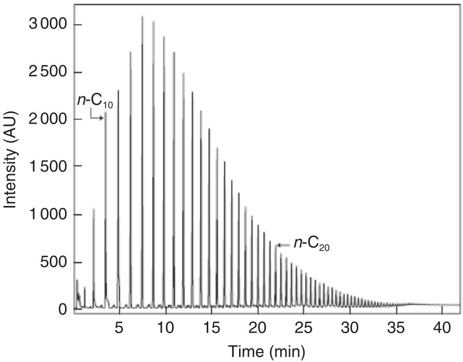
Figure 1 - Typical hydrocarbon distribution in FT liquid sample by LR-GC [1]
The above reactions are very exothermic, and practical operation is limited to roughly 200–350 °C and 10–40 bar because methane formation becomes excessive at temperatures above about 400 °C:
CO + 3 H2 ⇔ CH4 + H2O
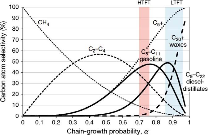
Figure 2 - Affecting Alpha (Probability of Chain Growth) according to the ASF Model: Temperature, Catalyst, Activity, Pressure, etc, with regimes for the chain growth probability for the commercial HTFT and LTFT [2]
Solid carbon (coke) formation is another secondary, undesired reaction that becomes more problematic as temperature and severity increase:
2 CO ⇔ C(s) + CO2
Secondary reactions including methane formation, alcohol formation and coke deposition reduce selectivity to liquids and impact catalyst life. Industrial catalysts are based mainly on cobalt and iron, often supported on oxidic carriers and promoted to adjust activity and selectivity; cobalt is typically preferred for H2-rich syngas from natural gas, whereas iron is widely used with coal/biomass-derived syngas because it can catalyze water–gas shift and thus accommodate lower H2:CO ratios:
CO + H2O ⇔ H2 + CO2
 |
 |
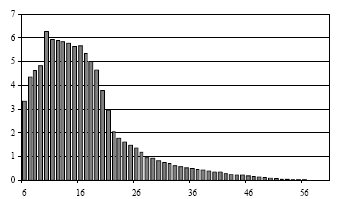
Iron catalyst: 30 bar, 280 °C
High selectivity of C10-C18
(high yield of diesel fuel) |
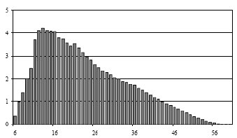
Cobalt catalyst: 30 bar, 240 °C
Wider distribution
(heavier products produced) |
Figure 3 - Product Distribution charts:
x-axis: chain length; y-axis: percentage on weight [2] |
Recent mechanistic work has revealed that under certain conditions, particularly on cobalt-based catalysts supported on reducible oxides, FT can exhibit oscillatory behavior in reaction rate and selectivity arising from coupled thermokinetic feedback, but this remains a research topic rather than a commercial design basis. Classical isothermal reactor and kinetic models remain the foundation for industrial FT reactor design and scale-up.
Products and upgrading
The effluent from an FT reactor is a complex mixture of hydrocarbons spanning from C1–C4 gases through gasoline and kerosene/jet fuel to diesel and high-molecular-weight waxes, plus water and dissolved light oxygenates. The exact distribution depends on catalyst, reactor type and operating conditions, with high-temperature processes favoring olefinic gasoline-range products and low-temperature processes favoring paraffinic gasoils and waxes.
Because the raw product rarely matches final fuel specifications, especially in terms of volatility and cold-flow properties, an additional hydroprocessing step is always required. This downstream section typically includes fractionation, hydrotreating and hydrocracking/isomerization of heavier fractions, converting waxy paraffins into diesel, jet fuel and gasoline that meet market standards, while preserving the inherent advantages of FT fuels such as near-zero sulfur and very low aromatics.
Reactors and process flow
Over time, four main reactor concepts have been used at industrial scale for FT synthesis, although licensors implement them in different proprietary designs. These are multitubular fixed-bed reactors, slurry bubble column reactors, fluidized-bed reactors and variants thereof, all engineered to manage strong exothermicity and maintain controlled temperature profiles.

Figure 4 - Four main Fischer-Tropsch Reactor Types [3]
A generic FT process flow, independent of feedstock, comprises syngas generation and cleaning, FT synthesis in one of these reactor types, primary cooling and phase separation, and product fractionation and upgrading. Syngas is produced upstream via gasification (for coal, biomass, residues) or reforming/partial oxidation (for natural gas or light hydrocarbons), then cleaned of particulates, sulfur, halides and tars, and adjusted in H2:CO ratio before entering the FT reactor. The FT section operates typically in a low-temperature or high-temperature regime, with pressure chosen to balance catalyst performance, heat removal and compression cost, and the hot effluent is cooled to condense water and hydrocarbons for separation into gas, liquid and aqueous streams.
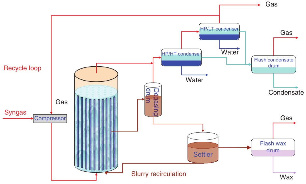
Figure 5 - Fischer-Tropsch Simplified Process Flow Diagram [1]
The liquid hydrocarbons are then distilled and routed to hydroprocessing units (hydrocracking, isomerization, hydrotreating), while off-gas is recycled or used as fuel, and process heat is recovered through steam generation to improve overall energy efficiency. This integrated configuration is common to coal-, gas-, biomass- and waste-derived FT plants and allows the FT section to be treated as a synthetic crude oil producer feeding a downstream refinery-like upgrading block.
Utility, economics and environmental aspects
FT diesel and jet fuel are attractive because they contain almost no sulfur and have very low aromatic content, resulting in high cetane numbers for diesel and favorable properties for aviation fuel when properly blended and specified. These properties ease compliance with stringent fuel regulations and can improve local pollutant emissions, but they do not automatically imply low greenhouse-gas intensity, which depends on the upstream feedstock and carbon management strategy.
FT plants are capital-intensive, especially when including gasification or large-scale reforming, extensive gas cleaning, FT reactors and upgrading units, so they are generally competitive only when alternative routes to fuels are constrained or when low-cost or stranded feedstocks are available. For coal-based FT, energy security can be improved for coal-rich, oil-poor countries, but total CO2 emissions per unit of fuel can be significantly higher than for conventional petroleum refining unless carbon capture and storage or biogenic feedstocks are employed.
Technologies and market references
Across the literature, FT is applied in three main feedstock routes: coal-to-liquids (CTL), gas-to-liquids (GTL) and biomass- or waste-to-liquids (BTL/WtL), all using the same core FT step but differing in syngas generation and overall carbon footprint. Large CTL complexes in South Africa use iron-based FT to convert coal-derived syngas to fuels and chemicals, while GTL plants based on natural gas commonly employ cobalt-catalyzed low-temperature FT to produce diesel and naphtha.
Biomass- and waste-based FT projects, including those described in recent reviews and SAF-focused articles, combine biomass or waste gasification, thorough gas cleaning, FT synthesis and tailored upgrading to produce synthetic diesel and aviation fuel with biogenic or partially biogenic carbon content. Current and planned projects associated with various licensors demonstrate FT deployment at scales ranging from demonstration units to large commercial plants, and the technology portfolio includes both established designs for CTL/GTL and newer configurations optimized for synthetic aviation fuel production.
Proprietary Technologies and Comparison Summary
| Licensor |
Technology Name |
Reactor Type |
Catalyst |
Scale Focus |
Primary Application |
| Sasol |
Sasol LTFT™ / SPD™ |
Slurry bubble column |
Cobalt (GTL), Iron (CTL) |
Large
(>10,000 bpd) |
GTL,
CTL, wax
|
| Shell |
SMDS |
Multitubular fixed-bed |
Cobalt |
Large
(>10,000 bpd) |
GTL,
specialty wax |
Johson Matthey
& BP |
FT CANS™ |
Fixed-bed with
enhanced tubes |
Proprietary |
Large (SAF /
renewable diesel) |
BTL,
WtL,
SAF |
Topsoe
& Sasol |
G2L™ |
Integrated (Sasol LTFT) |
Cobalt / Iron |
Large to
mega-scale |
GTL,
BTL,
PtL |
| Velocys |
microFTL™ |
Microchannel |
Oxford-engineered |
Small to medium (modular) |
SAF, renewable diesel, eFuels |
| Synfuels China |
HTFT / LTFT slurry |
Slurry bed |
Iron |
Large (mega-scale CTL) |
CTL |
| Greyrock |
Distributed
FT |
Modular integrated |
Proprietary |
Very small (5–2,000 bpd) |
Distributed GTL |
References
- Boyer C. et al.. Development of the Fischer-Tropsch Process: From the Reaction Concept to the Process Book. Oil & Gas Science and Technology - Revue d’IFP Energies nouvelles, 2016, 71 (3). DOI: 10.2516/ogst/2015032. hal-01395119
- Jay. Gas to Liquids (2012). All Power Labs
- Fischer - Tropsch Process (accessed on Dec 25, 2025). Biofuels Academy
- Proceso Fischer-Tropsch (accessed on Dec 25, 2025). QUIMICA.ES
- Fischer–Tropsch process (page updated on Sep 26, 2025). Wikipedia
- Hu J. et al.. Application of Fischer–Tropsch Synthesis in Biomass to Liquid Conversion. Catalysts 2012, 2, 303-326. DOI:10.3390/catal2020303. ISSN 2073-4344
- Technology (accessed on Dec 25, 2025). SASOL
- Scaling up SAF production with Fischer Tropsch technology (Apr 10, 2024). Hydrocarbon Processing
- Fischer-Tropsch wax upgrading (accessed on Dec 25, 2025). Topsoe
- Steynberg A.P. et al.. High temperature Fischer–Tropsch synthesis in commercial practice (Oct 2, 1999). Applied Catalysis A: General, 186(1–2), 41-54. DOI: 10.1016/S0926-860X(99)00163-5. ISSN 0926-860X
- Press Release: Johnson Matthey and bp technology chosen for the world’s largest Fischer Tropsch SAF production plant (Apr 10, 2024). Johnson Matthey